Current design: F-450 R1
Adam selected an F-450 crew cab 4x4 as the tow-platform ceiling. R1 replaces the R0 axle, capacity and motion assumptions.
Open the current R1 mechanical model, load cases and plansThis page preserves the R0 brainstorming archive. Its calculations and artistic renderings do not define the current design.
Engineering concept and RFQ baseline. The full-capacity trailer requires a suitable commercial tow platform. F-350/F-450 operating envelopes are unapproved. Final structural and fabrication drawings remain to be engineered.
Explore the geometry and hitch load
Change inputs to see why deck position and cargo placement matter. These equations use a simplified rigid trailer model and do not approve a load.
Hitch x=1.5 ft provisional. Three-axle resultant x=34 ft; two-axle x=36.25 ft is an equal-sharing assumption. No independent axle-load result is calculated.
Six angles
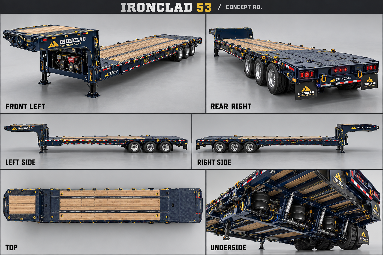
Concept rendering. Open for full resolution. Exact kinematics and ratings require the plans and engineering release.
Tail down, main raised, upper transfer
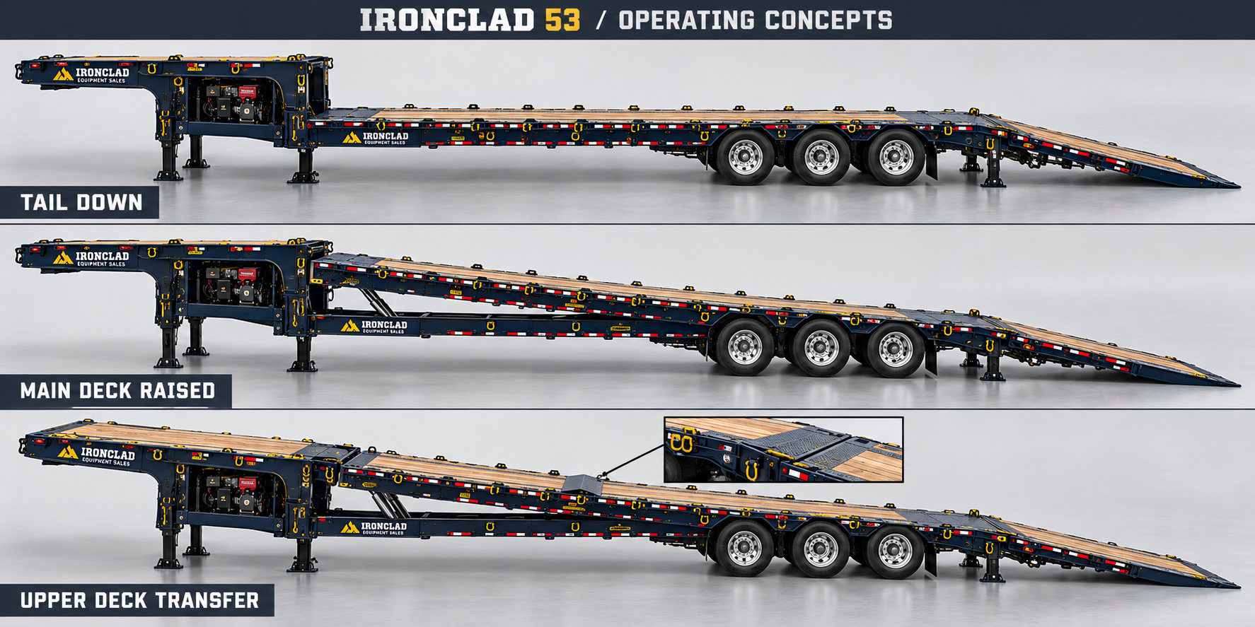
Concept rendering. Open for full resolution. Exact kinematics and ratings require the plans and engineering release.
Mini fleet and TB260 + TL12V2
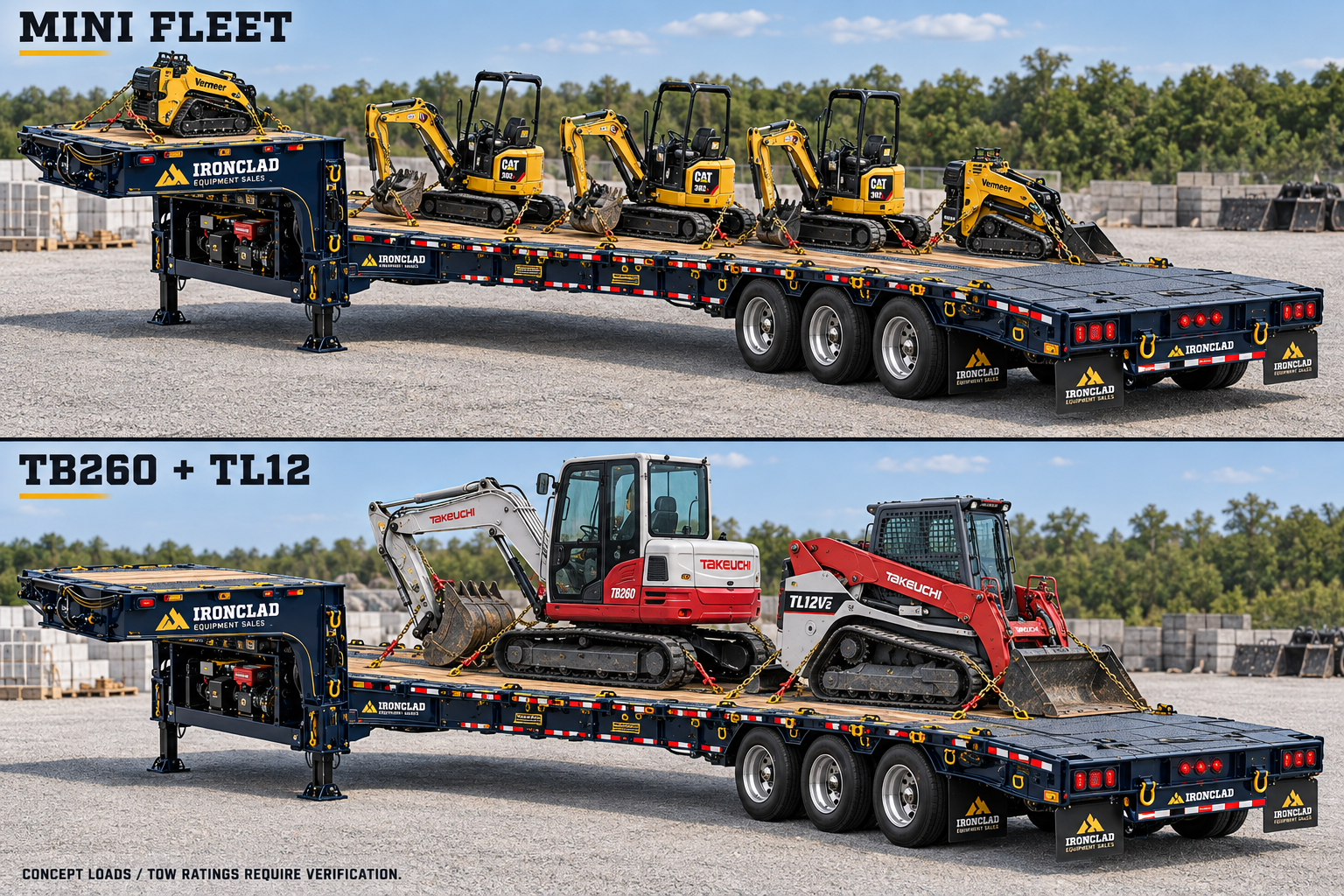
Concept rendering. Open for full resolution. Exact kinematics and ratings require the plans and engineering release.
Lift axle and loading lights
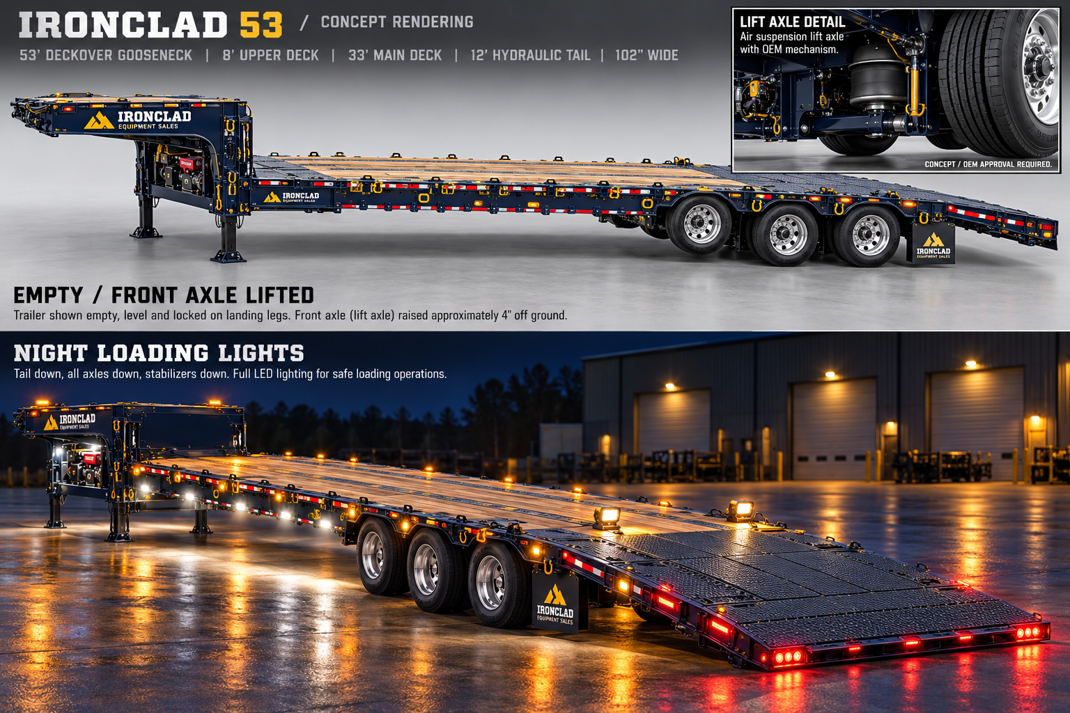
Concept rendering. Open for full resolution. Exact kinematics and ratings require the plans and engineering release.
Preliminary plan sheets
Jump to any design section
1. Project basis and release status 2. Design decisions 3. Dimensions and station convention 4. Kinematic solution and transfer bridge 5. Capacity definitions and weight budget 6. Load reactions and pickup feasibility 7. Frame, hinges and structural load paths 8. Actuator force calculation: the 20-ton tilt problem 9. Mechanical locks and service support 10. Hydraulic power unit and machinery bay 11. Hydraulic circuit and valve inventory 12. Hoses, fittings and moving-joint routing 13. Winches and cable management 14. Air suspension, lift axle and onboard air 15. Road brakes and brake independence 16. Cargo anchors, rails and decking 17. Lighting inventory and camera placement 18. Electrical architecture and energy budget 19. Wireless controls, sensors and state machine 20. Operating sequence and failure cases 21. Loaded layout plans 22. Procurement strategy and budget allowances 23. Engineering release gates and prototype plan 24. Florida use and transport classification 25. Supplier RFQ questions and next decisions 26. Source register01 Project basis and release status
IRONCLAD 53 - triple-deck hydraulic gooseneck. Revision R0, 1 October 2026. Owner: Adam Louramore / Ironclad Equipment Sales. This is the engineering concept baseline and supplier RFQ package. It includes preliminary calculations, layout plans and a procurement BOM. It is not released for fabrication or assigned a certified GVWR.
Preserve the full dream configuration: 53 ft overall concept length, 8 ft tilting upper deck, 33 ft tilting main deck with a 40,000 lb structural payload target, 12 ft hydraulic tail, three dual-wheel axles, air suspension and a forward lift axle. All requested lighting, cameras, winches, cargo track and wireless hydraulic controls are included.
Tow vehicles requested: existing F-350, possible future F-450. Neither vehicle is approved by this concept. Full-capacity service points toward a suitable commercial tow vehicle and connection. Pickup operation is a separate, reduced-load envelope requiring actual truck labels, scale tickets, geometry and hitch limits.
All capacities called targets or candidates below remain provisional. Manufacturer ratings apply only to their specified assemblies; they do not certify this custom trailer. Rendering proportions and visible hardware are illustrative. Dimensioned schematic sheets and calculations govern the concept.
02 Design decisions
| System | R0 decision | Unresolved release requirement |
|---|---|---|
| Frame | Fixed chassis under independently tilting main deck | Beam sections, weld fatigue, torsion, axle mounting |
| Axles | Three Dexter D160 / DexAir 16K-class assemblies; 12 road tires | OEM approval of lift kit, axle spacing, track and brake controls |
| Main deck | Rear pivot at station 41 ft; front rises | 40K payload load envelope and actuator geometry |
| Upper deck | Rear pivot at station 8 ft; front rises to match main slope | Truck cab sweep and 4K preliminary upper load target |
| Tail | Coaxial rear pivot on fixed rear crossmember; independent movement | 14K single-machine traversal target; 10K carrying target |
| Transfer bridge | Captive telescoping / hinged plate; 24 in nominal span | Minimum supported overlap and point-load proof |
| Power | Honda iGX800 EFI; variable-flow or two-speed hydraulics | Engine/pump/compressor matching and thermal duty |
| Controls | Industrial hold-to-run wireless + wired pendant | Risk assessment, stop performance and fault testing |
| Wiring branch | New U.S. function-based system schematic | Actual connector, device ratings and harness release |
03 Dimensions and station convention
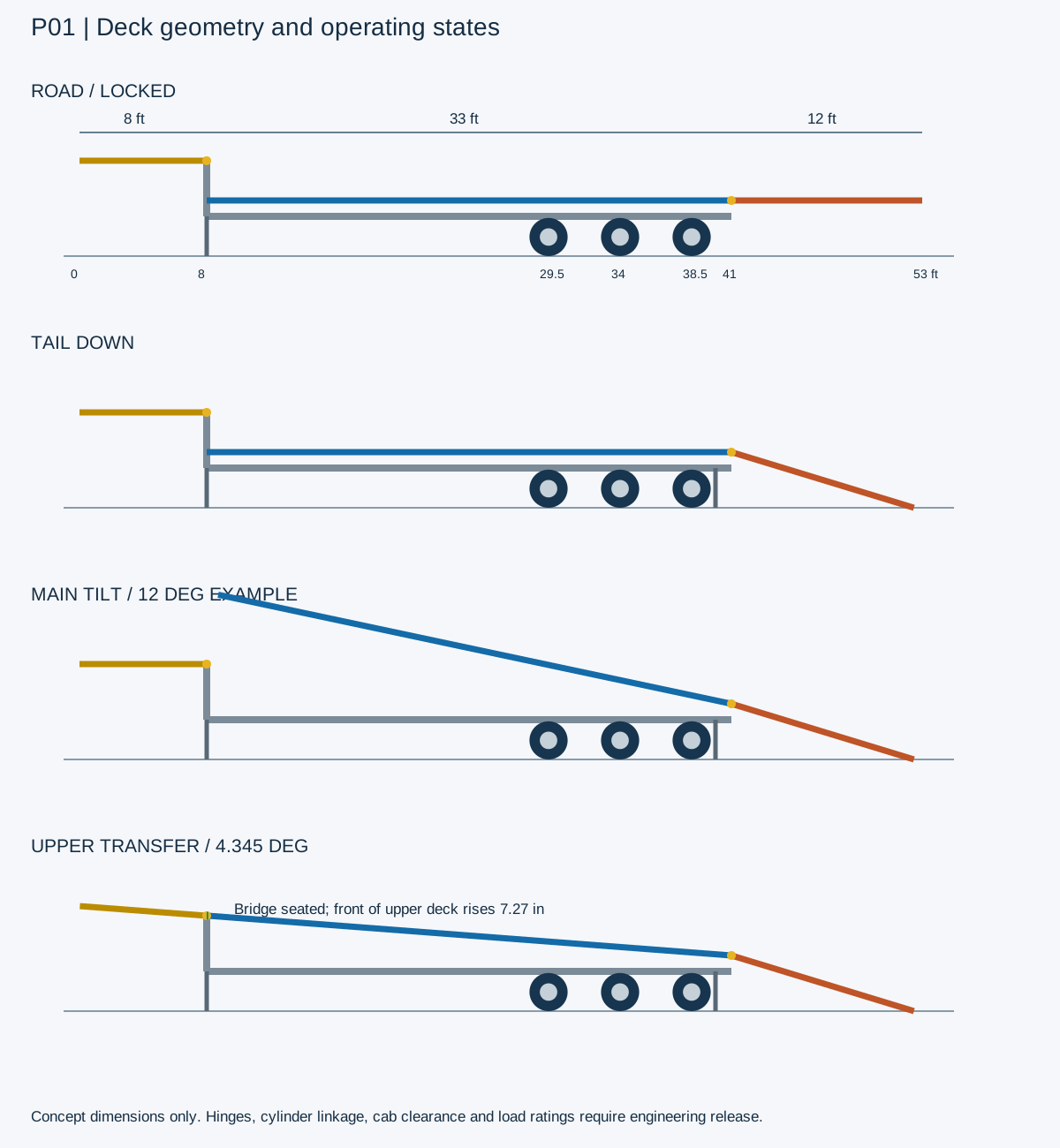
Use x = 0 at the forward edge of the upper deck, increasing toward the tail. The nominal upper zone is x=0..8 ft, main x=8..41 ft and tail x=41..53 ft. These nominal zones sum to 53 ft; hinge clearances, bevels and bridge overlap reduce uninterrupted cargo surface. Do not add the bridge as another advertised deck length.
The hitch center is provisionally x=1.5 ft, beneath the upper platform. This is a calculation datum, not an approved neck setback. The 53 ft outside envelope must include any coupler housing, bumper or stored hardware projecting beyond the deck. Any clearance-driven change requires a revised overall dimension.
Nominal main deck height 42 in at normal ride height; upper rear pivot height 72 in. Width target 102 in maximum outside envelope including rub rails and fixed hardware. Main flat-frame ground clearance, tire-to-deck clearance at full jounce, and belly breakover require CAD verification.
Axle centers: x=29.5, 34.0 and 38.5 ft; 54 in spacing, 108 in outer spread. Main/tail pivot at x=41 ft gives 30 in clearance behind rear axle center before the hinge. Tail road overhang is substantial: rear axle to tail tip is 14.5 ft. Tail swing, axle ratings, rear guard geometry and fatigue must be examined.
Upper front corners have a swept radius of approximately 4.51 ft from the provisional hitch (sqrt(1.5^2+4.25^2)). A 72 in high upper deck cannot be assumed to pass over a pickup cab. Check cab, bed, tailgate, safety chains and loaded upper-deck contents through the full turn, pitch and roll envelope before committing neck geometry.
| Parameter | Nominal |
|---|---|
| Overall external target | 53 ft / 636 in |
| Upper zone | 8 ft / 96 in |
| Main zone | 33 ft / 396 in |
| Tail zone | 12 ft / 144 in |
| Main width | 102 in outside maximum |
| Main pivot height | 42 in |
| Upper pivot height | 72 in |
| Hitch station | 1.5 ft provisional |
| Axle stations | 29.5 / 34 / 38.5 ft |
04 Kinematic solution and transfer bridge
With the main rear pivot at 42 in, the main front must rise 30 in to reach the upper rear pivot at 72 in. Required main transfer angle = asin(2.5/33) = 4.345 degrees. Front moves aft 33*(1-cos(angle)) = 1.138 in. This small arc gap is distinct from fabrication clearances and hardware recesses.
Keep the upper rear pivot fixed. Raise its front so the upper surface falls toward the rear at the same 4.345 degrees. Upper front rises 8*sin(angle) = 7.273 in. The upper deck and main deck now share a slope. This is the proposed solution to transferring small machines upstairs.
Bridge candidate: full usable-width traction plate, roughly 24 in long, on captive slides at upper rear edge; controlled extension 0..12 in with hinged floating toe. Engineer bearing overlap, torsion, edge stiffness and retention. Bridge must seat on reinforced main-deck pockets; it must not carry equipment on cylinder force or friction alone.
Transfer motion limits: target one machine at a time, at most 4,000 lb upper/bridge load pending validation. No machine straddles either articulation while any deck moves. Main and upper reach verified angle tolerance (initial target +/-0.25 degree), then bridge extends and engagement sensors confirm bearing. Close transfer only after bridge retracts and all cargo is clear.
For general main-deck tilt, the front may rise to a provisional 12 degrees: front elevation = 42+396*sin(12 deg) = 124.3 in. This is not a matching-upper-deck position. The bridge remains stowed. Main underside, cylinders and loaded equipment sweep must clear the fixed chassis and machinery bay.
Tail-down angle at nominal main height is asin(3.5/12) = 16.96 degrees. Its grounded tip is x=41+12*cos(angle)=52.48 ft. Air kneeling to a validated 36 in pivot height would reduce the tail slope to 14.48 degrees. Neither is a low-angle claim; check each machine approach and breakover geometry. A captive 24..36 in ground toe extension is a useful option, not part of the nominal 53 ft transport envelope.
05 Capacity definitions and weight budget
20 US short tons means 40,000 lb cargo. A 40K deck target is not a 40K GVWR. Preliminary tare planning range is 16,000..22,000 lb; the worked examples use 18,000 lb. These are engineering allowances, not measured weights. At 40K cargo, gross trailer mass is approximately 58K in the example.
Three 16K axles provide 48K component capacity when assembled exactly as approved. With a 9 ft outer spread, FHWA published bridge-table guidance gives 42,500 lb for the three-axle group. Check every consecutive axle group in the truck/trailer combination, all individual axles and actual routes; mechanical capacity is not road permission.
Tail target: traverse one machine up to 14K with the tail grounded and stabilizers deployed; carry up to 10K distributed on the locked horizontal tail. These are separate new-design targets. Diamond C reports 10K distributed lift/carry for its own 12 ft tail; that rating cannot be transferred to this design.
Upper target: 4K total payload, low-profile cargo only, with load-placement and height limits. Top deck cargo is carried mostly by the hitch. Keep upper deck empty for initial trials and any pickup envelope until a measured load model is approved.
| Non-overlapping mass allowance | Low lb | High lb |
|---|---|---|
| Fixed chassis and neck | 4500 | 6000 |
| Moving main deck | 2600 | 3500 |
| Tail and ground toe | 1400 | 2000 |
| Upper deck and bridge | 650 | 1000 |
| Running gear, wheels, suspension | 3300 | 4200 |
| Hydraulic machinery, fuel, oil, tanks | 1100 | 1700 |
| Locks, legs and stabilizers | 900 | 1500 |
| Decking, anchors, wiring, lights, covers | 1550 | 2100 |
| TOTAL ESTIMATE | 16000 | 22000 |
06 Load reactions and pickup feasibility
Flat trailer preliminary rigid-body model: hitch H=xh=1.5 ft; supported axle-group resultant A=34 ft with all axles down. For each mass Wi at longitudinal CG xi: Rh=sum[Wi*(A-xi)/(A-H)]; Ra=sum(Wi)-Rh. This does not determine individual air-suspension axle reactions or truck front/rear axle loads; those require actual suspension and truck geometry.
Use assumed tare 18K at x=26 ft. Empty hitch reaction is 4,431 lb and axle reaction 13,569 lb. Lift the forward axle and assume remaining axle-group resultant x=36.25 ft: empty hitch rises to 5,309 lb. Do not authorize empty F-350 towing from trailer gross weight alone.
Worked heavy load: cab TB260 12,645 lb at assumed CG x=17.6 ft; cab TL12V2 13,190 lb at assumed CG x=33.85 ft. Cargo 25,835 lb, gross 43,835 lb, hitch approximately 10,873 lb and trailer axle group 32,962 lb. Published operating weights are planning inputs; buckets, thumbs, fuel, tracks and transport configuration require scale verification. The TL12V2 is the conservative named variant for the rendering; the user has not specified TL12 model year.
The 43,835 lb example exceeds Ford's advertised best-case 40,000 lb F-450 gooseneck tow rating before accessory-weight refinements. That rating applies to a specified regular-cab 4x2 DRW high-output diesel/package combination. The example hitch load is also a serious pickup payload/GAWR constraint. No F-450 or F-350 approval is implied.
Worked small-machine visual load: three 4,400 lb mini excavators at assumed CG x=12.5,21,29.5 ft; one 2,200 lb mini skid at x=37 ft and one 2,200 lb mini skid at upper x=4 ft. Gross 35,600 lb; hitch approximately 11,538 lb. This shows why the upper deck needs a real load map even when gross weight is below an advertised tow rating.
40K main-deck distributed cargo at x=24.5 ft gives example gross 58K, hitch 16,123 lb and axle group 41,877 lb. This is close to the bridge-table group limit and requires a rated commercial connection and suitable truck. Any nose-biased point load, extra tare or different suspension equalization changes the result.
Pickup envelope is gated by the minimum of actual tow rating, GCWR minus actual truck weight, available truck GVWR/GAWR/tire margins, coupler/hitch GTW and vertical rating, trailer certification, axle-group limits and cargo placement. If the dream chassis is too heavy even empty, build a separately engineered lighter derivative; do not fake compatibility by moving cargo until the hitch is unloaded.
| Example / all assumed CGs | Gross lb | Hitch lb | Axle group lb |
|---|---|---|---|
| Empty, 3 axles down | 18000 | 4431 | 13569 |
| Empty, front axle up | 18000 | 5309 | 12691 |
| TB260 cab + TL12V2 cab | 43835 | 10873 | 32962 |
| Three minis + two mini skids | 35600 | 11538 | 24062 |
| 40K main cargo at x=24.5 | 58000 | 16123 | 41877 |
07 Frame, hinges and structural load paths
Fixed chassis carries the neck, running gear, stabilizers and machinery. Moving main deck transfers road loads through engineered landing saddles, shear keys and positively locked restraints into the fixed chassis. Tail loads enter a shared rear hinge crossmember supported by both main chassis rails. The upper deck feeds a dedicated neck load path; it is not welded casually onto the cab-clearance structure.
Preliminary material family: weldable structural steel specified by the engineer, with certified plate for hinge lugs and locking shoes, machined pins with replaceable bushings and protected grease points. Beam flange/web thicknesses, pin diameters, lug spacing and weld sizes are deliberately not released at R0. Raw beam cut lengths in the BOM are zone lengths, not a shop cut list.
Analyze bending, lateral torsion, local track loading, braking, cornering, road shock, winch reaction, anchor pull, rear overhang fatigue and one-sided loading. Do not rely on a simple uniformly distributed 20-ton beam calculation. Track pressure, wheel/track entry impact and tiedown pull introduce local loads.
Anchor slots go in engineered replaceable outer anchor rails or reinforced diaphragms. Do not flame-cut chain slots into primary beam tension flanges. Use radiused openings, adequate ligament and accessible welds. Rub rails and stake pockets are cargo restraints only when explicitly designed and rated as such.
Stabilizer feet at rear pivot and twin hydraulic landing gear provide a stationary support polygon. Ground-bearing capacity and possible hitch uplift during loading must be evaluated. Keep coupled to a properly braked truck when required by the approved loading plan; landing gear and chocks do not substitute for a loading-stability analysis.
08 Actuator force calculation: the 20-ton tilt problem
Worst illustrative main moment about rear pivot: 40K concentrated at the front of a 33 ft deck gives 1,320,000 ft-lb. Add a 4K moving-deck allowance at 16.5 ft: total 1,386,000 ft-lb, before dynamic, friction and design margins. Actual moving mass is to be measured.
Two 8 in bore cylinders at 3,000 psi create about 301,593 lb total ideal extension force. With an illustrative mechanical efficiency of 0.85, the required effective perpendicular lever arm for that front-loaded case is 5.41 ft. This is difficult beneath a 42 in deck and cannot be assumed from a pretty rendering.
For 40K payload at x=24.5 ft, payload moment is 660,000 ft-lb and deck allowance 66,000 ft-lb. Required effective arm for the same cylinders is 2.83 ft before final margins. At x=20 ft it rises to 3.53 ft. A deck may carry 40K yet have a much narrower powered-tilt load envelope.
Design candidate is a rear-pivot deck driven through synchronized bellcranks / scissor linkage with twin custom cylinders. Linkage must maintain positive mechanical advantage at startup and throughout stroke. Candidate bore range 8..10 in is for engineering comparison only. A direct shallow-angle ram may be inadequate. Final bore, rod, stroke, trunnions, column buckling, pin bearing and mounting welds require kinematic force curves.
Illustrative stroke-volume check only: two 8 in bore cylinders with 45 in extension need approximately 19.6 gallons into cap ends; at 8 GPM this takes 147 seconds ideally. That is not an approved cylinder stroke. Regenerative or staged circuits must not sacrifice load control. Angle feedback and individual-cylinder balancing are required to prevent deck racking.
09 Mechanical locks and service support
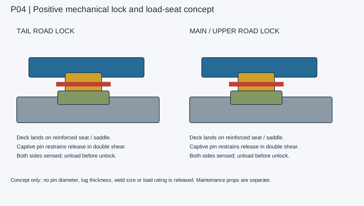
Use a positive load-bearing architecture rather than a claim of the industry's single best lock. Each system needs hardened load seats, captive pins or wedges, independent left/right engagement sensing and visible indicators. Hydraulic valves prevent uncontrolled motion during operation; mechanical seats and locks carry road loads.
Tail road position: paired tapered landing shoes seat on reinforced rear chassis pockets. Captive double-shear pins prevent upward release, with protected retainers and spring-biased engagement where geometry permits. Lift the tail just enough to unload pins before retracting. Recheck both sides before lowering. Do not support a 10K tail load only on cylinder pressure.
Main flat position: multiple chassis saddles carry vertical load; front and rear shear keys resist longitudinal/lateral loads; paired positive locks restrain uplift. Upper flat position: neck-mounted saddles, rear hinge retention and paired positive restraints. Bridge stowed position: captive latch plus secondary retaining feature.
Service access: pinned rated maintenance props for main, upper and tail, each installed from outside the crush zone. Props are separate from road locks. Use lockout, pressure release and load removal before entry. Design prop attachment so accidental hydraulic commands cannot eject the prop.
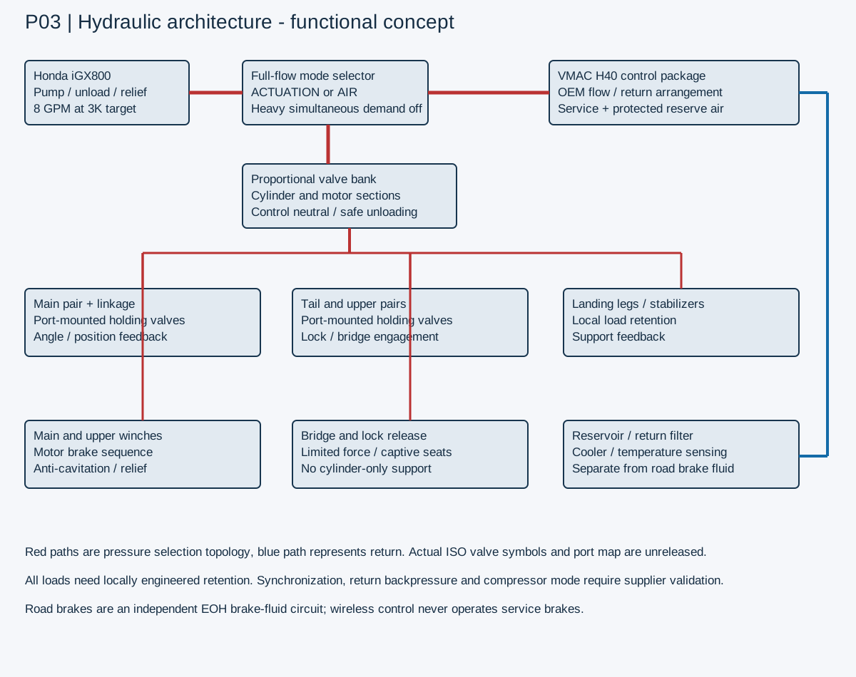
Cylinder-mounted counterbalance/load-holding valves on every load-driven circuit, controlled hose-burst response and protected hose routing remain essential. An electrical emergency stop must arrest motion without releasing a loaded deck; turning every valve off indiscriminately can create unsafe pressure transients.
10 Hydraulic power unit and machinery bay
Preferred engine candidate: Honda iGX800 EFI with electric starting and electronic speed control. Manufacturer lists 24.9 net hp at 3,600 rpm. Enclosed installation, ambient heat and accessory loads reduce usable hydraulic power; reserve an initial 22 hp shaft budget before detailed cooling and alternator studies.
Pump candidate: 12 GPM maximum at low pressure, approximately 8 GPM working flow at 3,000 psi for deck operations, via suitable variable-displacement or automatically unloaded staged arrangement. Hydraulic hp = psi*GPM/1714. At 3,000 psi and 12 GPM, required hydraulic power is 21.0 hp and estimated pump input at 85% efficiency is 24.7 hp, leaving virtually no engine margin. Do not call this a 12 GPM / 3,000 psi simultaneous duty system.
At 3,000 psi and 8 GPM, hydraulic power is 14.0 hp and estimated input 16.5 hp. At VMAC H40 reference operating point 2,345 psi and 9 GPM, hydraulic power is 12.3 hp and estimated input 14.5 hp. Operate the compressor separately from heavy deck or winch motion. Actual engine torque curve, pump speed ratio and compressor startup need supplier matching.
Bay concept envelope: 72 in wide x 36 in fore/aft x 30 in high, centered between landing gear in the neck transition before the main deck. This bay occupies vertical/under-neck space within the 53 ft envelope. Verify it does not invade truck rear clearance, main-deck lift sweep or winch line path. Bay size may need growth after actual packaged CAD.
Provide vented removable panels, guarded exhaust directed away from truck and operators, flame-resistant heat shield, service isolation, fuel shutoff, spill tray, extinguishing provision and corrosion-resistant fasteners. Avoid a sealed toolbox around an air-cooled Honda. Cooler airflow must discharge outside the bay without recirculation.
Reservoir candidate: 40 gallon shell with approximately 30 gallon working fill, baffles, diffuser, level/temperature indicator, filtered breather and drain. Target 10 micron return filtration with clog indicator; final cleanliness rating follows valve/pump makers. Cooler allowance 25..40K BTU/h subject to a thermal duty calculation and ambient-temperature test. Relief flow is not a continuous operating mode.
Use separate motor and cylinder manifold galleries where needed. Winch motor circuits require manufacturer brake sequencing, anti-cavitation and cross-port relief; load-bearing deck circuits require local holding valves. No tee fitting should defeat the compressor's control manifold. Use a full-flow diverter with proven neutral/unload state to select compressor or actuation service.
11 Hydraulic circuit and valve inventory
| Circuit ID | Function | Candidate hardware / requirement |
|---|---|---|
| H01 | Main deck twin cylinders | Proportional DA valve; cylinder-local holding valves; synchronized position feedback |
| H02 | Tail twin cylinders | Proportional DA valve; controlled lowering and two holding valves |
| H03 | Upper deck twin cylinders | Proportional DA valve; constrained transfer angle |
| H04 | Bridge extension | DA valve; relief-limited force; seat and stow sensors |
| H05 / H06 | Left / right landing gear | Independent control, simultaneous option with feedback |
| H07 / H08 | Left / right rear stabilizers | Controlled seating, holding valves, load/position sensing |
| H09 | Main 20K-class hydraulic winch | Motor spool matched to winch brake; relief and rated fairlead |
| H10 | Upper 8K-class hydraulic winch | Motor spool; force limited to upper/bridge support envelope |
| H11 | Compressor supply | Full-flow selector; OEM H40 control manifold |
| H12..H17 | Six deck-lock release mechanisms | Low-volume circuit with pressure reduction; each engagement sensor |
| H18 | Optional ground toe | Actuation/latch only; separately engineered load support |
12 Hoses, fittings and moving-joint routing
Preliminary concept sizes: pump-to-selector and high-flow motor feed 3/4 in class; high-flow return 1 in class; deck cylinder work lines 1/2..3/4 in class; low-flow lock lines 1/4 in class. These are velocity/pressure-drop starting points, not order sizes. At 8 GPM, a 3/4 in ID line is about 5.8 ft/s; at 12 GPM about 8.7 ft/s. Size with measured route lengths, cold viscosity and component limits.
Use pressure-rated assemblies, fittings and seals compatible with selected oil, temperature and pressure including spikes. Proposed work pressure 3,000 psi does not establish every component's pressure rating. Ports and adapters are finalized from manufacturer CAD; the BOM avoids fake universal part numbers.
Run fixed hard lines inside protected service channels on the chassis. At main, upper and tail pivots use guarded flexible loops or energy chains with full-stroke bend-radius allowance. Place holding valves as close to cylinder ports as practical so the hose is not the load-retention boundary. Avoid rubbing hoses through chain slots or against tire sweep.
Keep hydraulic work lines separate from road-brake hard lines and electrical loom. Provide bulkhead labels, abrasion sleeves at contact risks, restrained fittings, inspection access and drainage. Do not mix road-brake fluid plumbing with hydraulic lift oil.
13 Winches and cable management
Main winch candidate: Ramsey RPH/Helios 20K-class hydraulic planetary family with manufacturer-approved holding brake. Mount near the main deck nose with its reaction tied to both chassis rails. Upper winch candidate: Ramsey H-246 8K-class or appropriate industrial equivalent, located in a protected upper forward recess.
Actual line speed and pull depend on motor flow, pressure and cable layer. First-layer 20K is not 20K on every layer. Select drum, cable diameter/length, fairlead, fleet angle and duty from the current manual. A winch is not a crane and does not replace road tiedowns.
Use separate retractable fairleads and positive line-routing gates to avoid rubbing a cable on moving deck hinges. Clear the cable from all bridges before deck movement. Provide low-speed creep for upstairs transfer with pull limit tied to the upper and bridge load envelope.
Illustrative rolling pull: F=W*(sin(angle)+mu*cos(angle)). At 17 degrees with mu=0.08, F is about 0.369*W, before breakout and losses. A 14K rolling machine needs about 5.2K lb in this simplified model. Seized tracks, a snag, deep soil or a doubled line change both pull and mounting reactions. Engineer fairlead/support structure for worst permitted reaction.
14 Air suspension, lift axle and onboard air
Dexter D160 is a useful primary candidate because its published system supports air suspension, triple axle layouts, hydraulic disc brakes and dual wheels. A front lift conversion is not automatically approved. Ask Dexter for a rated liftable variant or an approved integrated package before buying axles. Hendrickson liftable families illustrate alternate approaches; do not graft an unmatched lift mechanism onto a D160 beam.
Use all three axles down for loaded road operation and all deck movement. Lift only on command after low-load verification, speed/state interlocks and a truck hitch-load check. Load-estimating air pressure must be calibrated against scales and suspension geometry. Loss of controller power should command axle-down or hold a validated safe state; pneumatic plumbing must prevent abrupt uncontrolled axle movement.
Air supply candidate: VMAC H40 hydraulic rotary screw package, sized for 25..40 CFM class service plus suspension charging. Its current product page lists 9..12 GPM hydraulic supply and a minimum 6 gallon receiver recommendation. Specify two purpose-built 10 gallon receiver tanks as a starting layout: protected suspension reserve and service-air reservoir, with check/priority valves and independent drains.
Add aftercooler/dryer appropriate to duty, pressure switch, pressure protection, certified receiver relief valves, regulator and service hose reel. Setpoints are selected with the suspension/receiver manufacturers; 120..150 psi is a planning range, not a license to set any tank or air spring to 150 psi.
Install a smaller automatic 12/24 V maintenance compressor that can maintain parked suspension reserve without starting the Honda. Include emergency external fill port. Service air cannot exhaust the protected suspension reserve. Because road brakes are EOH hydraulic, suspension-air loss is not brake-air loss; it can still cause ground-clearance and handling problems.
Independent rear stabilizers carry loading reactions. Suspension dump / kneel must be deliberately enabled only on firm level support, with adequate tire/deck clearance and no axle movement while personnel are in a pinch zone.
15 Road brakes and brake independence
Road braking uses a matched 12 V electric-over-hydraulic actuator and six hydraulic disc wheel-end brake assemblies. All three axles have brakes. D160/actuator supplier must approve total caliper displacement, line length, pressure, response, duty and brake-controller compatibility. A generic actuator advertised for three light axles is not automatically sufficient for three 16K axles.
Disc systems often use a 1,600 psi class actuator, but use the exact wheel-end and actuator specifications. Do not reuse lift-system pressure or oil. Brake lines get DOT-appropriate tubing/flex hoses, guarded axle-drop loops and separately routed fittings. Confirm ABS requirements and an integrated solution at this trailer's final classification and GVWR.
Keep a dedicated brake/breakaway battery, charging path and disconnect arrangement that cannot be disabled by the house/master light switch. Breakaway must operate with engine off, empty house battery, failed wireless remote and truck disconnected. Battery size and required hold duration follow the approved braking system and applicable rules.
Wireless control governs stationary hydraulic machinery only. It must never modulate the service brakes. Truck brake-controller signal and dedicated breakaway switch are hardwired. Include diagnostic indication and physical mechanical parking/anti-roll provisions approved by the axle maker, plus correctly sized wheel chocks.
16 Cargo anchors, rails and decking
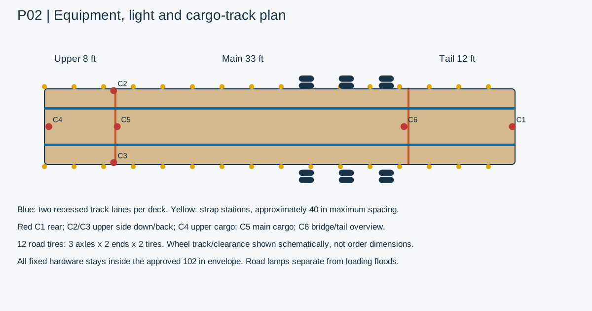
Provide two recessed longitudinal cargo-track lanes on each of upper, main and tail decks: 106 ft nominal total (2*53), subject to hinge cutbacks and local machining. Use a load-rated manufacturer system with fittings matched to the rail. Light cargo track serves light cargo; equipment chains attach to separately rated frame anchors.
Provide 4 in strap slider rails along both sides of all three zones. At maximum 40 in spacing, planning station counts including end locations are 4 per side upper, 11 per side main and 5 per side tail: 40 strap stations total. Final stations may be relocated around locks, hinges and tires while preserving access. Add edge protectors and positive strap stowage.
Initial anchor target: 24 heavy frame-tied D-rings total: 16 main, 4 tail, 4 upper, with upper rings separately limited by neck capacity. Add 24 reinforced chain-slot modules, primarily along the main rails. Target WLL is assigned from directional anchor proof and load path, not from ring size alone.
TB260/TL12 loads individually over 10K require heavy-equipment securement planning. FMCSA guidance calls for at least four tiedowns for wheeled/tracked heavy equipment plus appropriate securement of accessories. Check aggregate WLL, direction and all accessory restraint; do not count the winch cable as a tiedown.
Deck surface candidate: serviceable treated hardwood or engineered plank center, reinforced steel traction lanes at tire/track paths, sealed recessed-track drainage and bolt-access panels. Ground-contact tail/toe receives replaceable serrated traction grating. Pick plate/plank sizes only after local track pressure and axle-entry calculations.
17 Lighting inventory and camera placement
| Item | Quantity target | Placement / control |
|---|---|---|
| Road stop/turn/tail groups | 4 groups | Protected rear beam; approved visibility and mounting |
| Rear identification lamps | 3 | Center rear cluster for wide trailer |
| Front/rear clearance lamps | 4 | Outer corners; required color by position |
| Side road markers | 20 | About 10 per side; legal road-lighting plan governs |
| Plate lamp | 1 | Protected rear license location |
| Flush load floods | 8 | Four per side, aim inward/down; stationary enable |
| Underdeck service floods | 6 | Bay, legs, axle service areas; separately switched |
| Tail/loading floods | 4 | Shielded ramp hinge and underside aiming at ground |
| Portable magnetic floods | 4 | Tethered removable pods; charged in flush stow lockers |
| Amber warning modules | 8 | Rear four / side four; approved emergency/loading use |
| Rear backup camera | 1 | Center rear, guarded lens with cleanout access |
| Upper-side down/back cameras | 2 | Left/right upper outer rear corners |
| Upper cargo camera | 1 | Upper forward frame, aims rear/down |
| Main cargo overview | 1 | Protected neck, watches main deck and chains |
| Tail/bridge loading camera | 1 | Views hinge/bridge clearances; no safety interlock credit |
18 Electrical architecture and energy budget
Separate three domains: 12 V road lighting and brakes; 24 V house lighting/cameras/control; engine start/engine ECU supply per Honda. Use a documented ground/bond plan, dedicated return conductors and protected chassis bonds. Wireless/video failure does not disable road lighting or breakaway braking.
House battery candidate 24 V 100 Ah (2.4 kWh nominal), with protected BMS, temperature monitoring and a main fuse placed close to the battery. If 12 V batteries are placed in series, both must explicitly permit series use. Charger/source chemistry must match. Initial 80% usable-energy assumption gives 1.92 kWh.
Loading-light budget: 8x25W overdeck + 6x15W underdeck + 4x25W ramp + 4x15W portable charging = 450 W. Cameras/control allowance 70 W gives 520 W full-use demand, or 21.7 A at 24 V. Ideal useful runtime is about 3.7 h at that load, before cold/aging/conversion effects. Road lights are on their separate circuit.
Honda charging coil is not a large house alternator. Keep its intended engine-start/ECU duties unless the engine package supplier approves more. Candidate house charging: shore charger, fused isolated truck DC-DC charger sized to actual available supply, optional 400W solar and a belt-driven alternator only after shaft/accessory-load analysis.
Every branch gets an individual fuse matched to conductor ampacity and device inrush. Preliminary branch current estimates do not establish final fuse sizes. Compute voltage drop using actual round-trip length, copper resistance and continuous load. For a 100 ft loop at 5 A, 12 AWG copper at roughly 1.59 ohm/1000 ft drops 0.795 V, about 6.6% of 12 V; a long lighting run may need larger wire or multiple feeds.
Use sealed automotive connectors, tinned copper where appropriate, junction boxes with drip loops, mechanical strain relief and abrasion protection. Camera data and antenna leads avoid high-current motor/actuator wiring. Use wired Ethernet/AHD or industrial video links along the trailer with a wireless truck bridge if wanted; consumer wireless alone is poor assurance over 53 ft of steel.
19 Wireless controls, sensors and state machine
Industrial radio candidate families include safety-oriented mobile-machine controls from established suppliers; choose a current supported system with hold-to-run, authenticated pairing, defined loss-of-link response, emergency stop and wired backup. This document does not claim a Performance Level or SIL. Establish the necessary architecture from a machinery risk assessment.
Inputs: speed/parked verification; truck coupling status; all deck angles; bridge extended/stowed/seated; left/right lock engagement; landing-leg and stabilizer positions/loads; axle-up/down; air pressure; hydraulic pressure/temperature/level; battery voltage and optional payload/axle load sensors.
Outputs: proportional valve commands, enable/unload valve, engine start/stop permission, controlled RPM request, lock-release valves, air compressor request, axle-lift request and separate loading-light modes. Brake-controller and breakaway circuits bypass the motion controller.
ROAD state requires main/upper/tail locked, bridge stowed, legs/stabilizers retracted, loose lamps stowed and correct suspension ride state. Motion commands inhibited at road speed. EMPTY LIFT is a substate with calibrated load and hitch checks; it is not a default because the trailer is empty.
PREPARE LOADING requires stationary confirmation, firm level support, wheels/chocks and stabilizer placement according to the approved support plan. TAIL DOWN then MAIN LOAD or TRANSFER ALIGN follow. TRANSFER ALIGN verifies angle match and bridge bearing before granting creep winch movement.
Loss of radio: stop commanded movement and hold all loaded structures using local valves; a restart requires deliberate re-enable and fresh command. A stuck valve, sensor disagreement or one-sided deck motion triggers a safe stop with retained support. Camera pictures do not prove the bridge is seated. Use hard sensor confirmation and visible checks.
The remote has one deliberate active motion mode, labeled deck selection, proportional slow/fast command, lock-release hold and E-stop. Do not combine a deck unlock and uncontrolled lowering in one unlabeled button. Logs capture commands, sensed state, faults and completed lock confirmation for the OS service record.
20 Operating sequence and failure cases
| Step | Required action | Failure response |
|---|---|---|
| 1 | Park, inspect ground/clearance, establish support/chocks | Abort if support or truck hitch reactions are unknown |
| 2 | All axles down; suspension at loading state | Inhibit motion on axle/suspension disagreement |
| 3 | Unload tail locks, release, lower tail under control | Local holding valves retain load on hose/radio fault |
| 4 | For main loading choose validated tilt angle and load envelope | Stop on asymmetric cylinder travel |
| 5 | For upstairs transfer align main and upper near 4.345 deg | Bridge remains retracted until both angles verified |
| 6 | Extend bridge; verify both bearing seats; move one small machine | Stop winch on overload or bearing loss |
| 7 | Secure upper load; clear bridge and articulation; retract bridge | Do not tilt with machine straddling joint |
| 8 | Return upper/main/tail onto seats; confirm each road lock | Road-ready remains blocked if any side fails |
| 9 | Retract support hardware, stow lamps, inspect brakes and chains | Manual inspection before movement |
| 10 | Measure truck/trailer axle loads for first load map trials | Reduce load or change tow vehicle if any limit exceeded |
21 Loaded layout plans
Heavy rendering: one nice enclosed-cab TB260 and one enclosed-cab TL12V2 on the main deck, upper and tail empty. Published transport lengths approximately 18 ft 2.5 in and 13 ft 3.3 in sum to about 31.48 ft. Only 1.52 ft remains in a 33 ft nominal zone before hinge clearances and accessory changes. A real fit needs measured transport dimensions, machine orientation, bucket placement and safe separation.
Example footprint on main: TB260 from x=8.5 to 26.71 ft; TL12V2 from x=27.21 to 40.49 ft. CGs used earlier are assumptions inside those footprints. The heavy visual is a commercial-tow concept and is not an F-450-approved scene.
Mini fleet rendering: three small tracked excavators on main, one stand-on mini skid on main, one compact stand-on mini skid upstairs. Assumed main lengths 8 ft each plus a 6 ft skid with spacing fit within 33 ft only if measured boom/bucket configurations match. Upper mini skid assumed 6 ft footprint. Small-machine masses are placeholders until OS records and actual scales confirm.
Do not put the TB260 or TL12 on the upper deck. Do not carry a 13K TL12 on a tail with a preliminary 10K carrying target. Loaded road travel has every platform horizontal and mechanically locked, with front axle down. Check roof/bucket height above the 72 in upper deck and the complete road-height limit.
22 Procurement strategy and budget allowances
The CSV BOM lists system quantities and engineered requirements. Entries labeled candidate require supplier acceptance; fabricated entries need released drawings. Hoses, wire, hardware and steel allowances are estimating quantities. No final cut list or purchase-ready fastener/pin schedule is issued before structural sizing.
R0 planning allowances, not vendor quotes: frame/moving decks 28..45K USD; running gear/lift/brakes/tires 22..35K; hydraulic engine/pump/winches/cylinders/manifolds 20..35K; compressor/air supply 6..12K; electrical/control/cameras/lighting 8..16K; anchors/finish/guards 5..10K. Material/subassembly subtotal roughly 89..153K. Individual BOM allowances may differ as scope is refined.
Engineering and testing allowance 15..35K; custom fabrication 600..1,000 hours at an illustrative 100 USD/h = 60..100K; contingency 15..25% on the defined procurement/fabrication scope. This can readily become a 190..350K one-off project. A specialist trailer manufacturer may improve integration and price. Quotes, in-house labor and design simplification decide the real budget.
Buy complete rated running gear and brakes as a package. Design the rest around validated tire clearance and suspension height. Do not buy loose axles first then discover the lift/suspension/EOH combination cannot be approved. Obtain matching CAD and rated mount loads before frame release.
23 Engineering release gates and prototype plan
| Gate | Deliverable / evidence |
|---|---|
| G1 Truck and connection | Actual F-350/F-450 VIN/config labels; hitch install spec; commercial truck alternative; scale weights |
| G2 Geometry | 3D assembly; 53 ft envelope; turn/pitch/roll cab sweep; tire jounce; all deck swept volumes |
| G3 Structure | Load matrix; beam/local/anchor/hinge/pin calculations; fatigue assessment; qualified weld procedures |
| G4 Hydraulics | Actuator force vs angle/stroke; buckling; pressure-spike and hose-burst response; heat balance |
| G5 Running gear | OEM D160/DexAir lift acceptance; tire/wheel match; axle load sharing; lift logic |
| G6 Braking | EOH system validation, ABS/classification, controller compatibility, breakaway and stopping tests |
| G7 Controls | Fault tree; safety architecture; single-fault tests; loss-of-link/stuck valve/sensor disagreement |
| G8 Certification | Applicable FMVSS/label/VIN/state title, rear guard, road lamps and route assessment |
| G9 Prototype | Empty motion, ballasted incremental loads, independent calibrated reactions, lock proof and NDT |
| G10 Release | Rated load map by deck/state, inspected drawings, torque/weld schedule, user/service manuals |
24 Florida use and transport classification
Florida 316.515 distinguishes straight-truck/trailer combinations from truck-tractor/semitrailer combinations. The statute lists 68 ft overall for a straight truck with trailer and specific longer-semitrailer conditions. A pickup gooseneck must not be assumed to receive the same length treatment as a commercial tractor/semitrailer.
The published 2025 statute allows some semitrailers over 48 ft up to 57 ft under conditions including kingpin-to-rear-group geometry and rear underride protection. Confirm current classification and route application with FDOT/state authority for the actual build. A 53 ft trailer plus a pickup could create an overall-length issue even before weight.
Final rear guard must work with the tail-down mechanism. A folding/retracting guard needs positive road-position retention and a valid compliance assessment. The rear guard cannot be merely omitted because it interferes with loading. Required road lamps/reflectors remain visible and operational with the tail locked for travel.
At this size, evaluate commercial registration, brake standards, licensing and route/bridge constraints for the actual use. This report identifies design inputs; it does not issue a legal route approval.
25 Supplier RFQ questions and next decisions
| Recipient / decision | Exact question |
|---|---|
| Dexter or rated package supplier | Can you supply three D160 dual-wheel hydraulic-disc / DexAir axles with an approved forward lift axle at 54 in centers, plus matched EOH/ABS? Supply drawings, mount loads and pressure/volume requirements. |
| Hydraulic integrator | Can the iGX800 package support 8 GPM at 3K plus 9 GPM H40 mode, with no heavy simultaneous demand and required cooling? |
| Structural trailer engineer | Can 40K main payload be carried and tilted in the proposed 33 ft rear-pivot layout, and what CG/point-load restrictions are required? |
| Cylinder supplier | Quote cylinders only after force/stroke/column curves, mounting geometry and duty are supplied. |
| Trailer builder | Quote complete fabrication/certification with a 53 ft external envelope and three separately locking decks. |
| Owner decision | Choose full heavy-haul dream baseline or additionally develop a lower-tare pickup derivative. |
| Owner measurement | Truck hitch-to-cab/tailgate clearances; actual truck labels; machine footprints/weights; desired upper cargo maximum. |
26 Source register
| ID | Primary source / accessed 1 Oct 2026 |
|---|---|
| S1 | Dexter D160: https://www.dextergroup.com/d160 |
| S2 | Honda iGX800: https://engines.honda.com/models/model-detail/igx800 |
| S3 | VMAC H40: https://www.vmacair.com/product/hydraulic-driven-air-compressors/40-cfm-hydraulic-air-compressors |
| S4 | Ford F-450: https://www.ford.com/trucks/super-duty/2026/models/f-450-xl/ |
| S5 | FHWA bridge formula: https://ops.fhwa.dot.gov/freight/publications/brdg_frm_wghts/index.htm |
| S6 | Florida 316.515: https://www.flsenate.gov/laws/statutes/2025/316.515 |
| S7 | Takeuchi TB260 weight: https://www.takeuchiglobal.com/en/products (manufacturer product listing); archived U.S. brochures may have moved. |
| S8 | Takeuchi TL12V2 dimensions/weight: https://www.takeuchi-mfg.co.uk/tl12v-2-compact-loader/ (UK configuration; verify actual U.S. transport setup). |
| S9 | FMCSA securement: https://www.fmcsa.dot.gov/regulations/cargo-securement/cargo-securement-rules |
| S10 | Ramsey RPH20K: https://www.ramseyindustries.com/ramseywinch/product/rph-20000/ |
| S11 | Ramsey H-246: https://www.ramsey.com/product/h-246/ |
| S12 | Diamond C FAQ: https://www.diamondc.com/faq/ |
| S13 | NHTSA manufacturer portal: https://vpic.nhtsa.dot.gov/mfrportal/ |
| S14 | Hendrickson liftable comparison: https://www.hendrickson-intl.com/products/intraax/intraax-aal |