R1 supersedes R0 capacity, axle and motion assumptions. Provisional 33,000 lb gross ceiling; nominal 19,700 lb tare. Heavy single-machine cases have little margin. Not released for fabrication or road use.
Deck and cylinder geometry
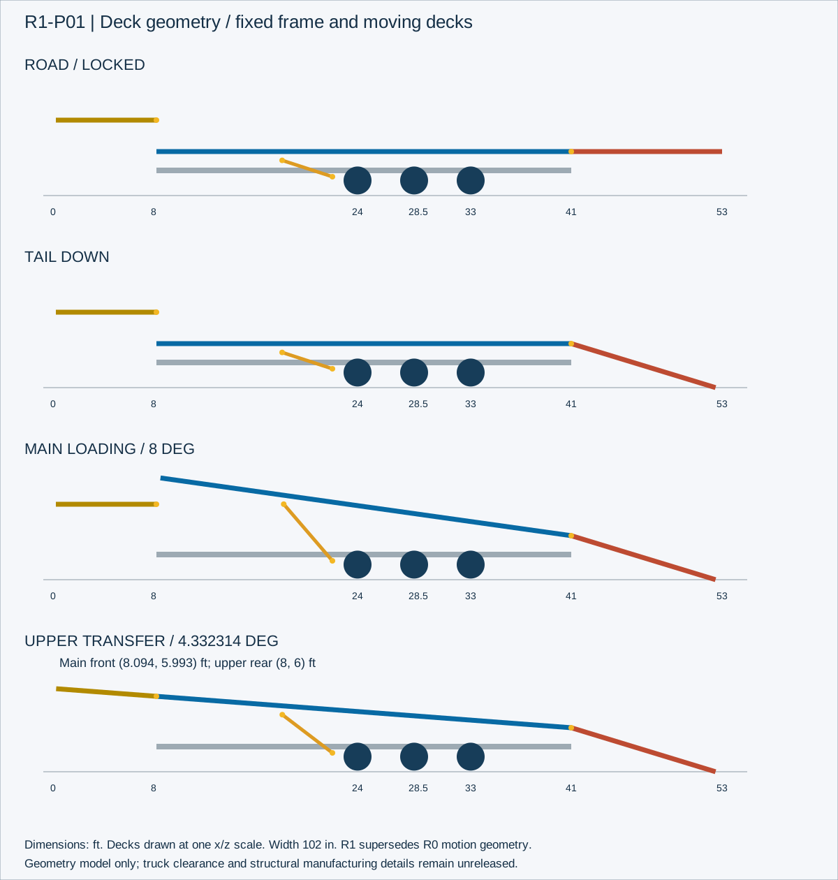
Geometry in feet at one x/z scale. Diagram is independent of the artistic R0 renderings. Trailer-to-truck clearance remains unresolved.
F-450 load envelope
5,000 lb pin capacity is an illustrative input, not a Ford rating. Enter the actual limit derived from truck weights, axle labels and hitch installation. Numerical screens do not approve a tow load.
Multiple main machines are represented by their combined mass and weighted CG. Upper cargo uses x=4 ft. Lift mode changes axle resultant from x=28.5 to30.75 and increases pin load; loaded lift is inhibited as a design requirement.
01 road model
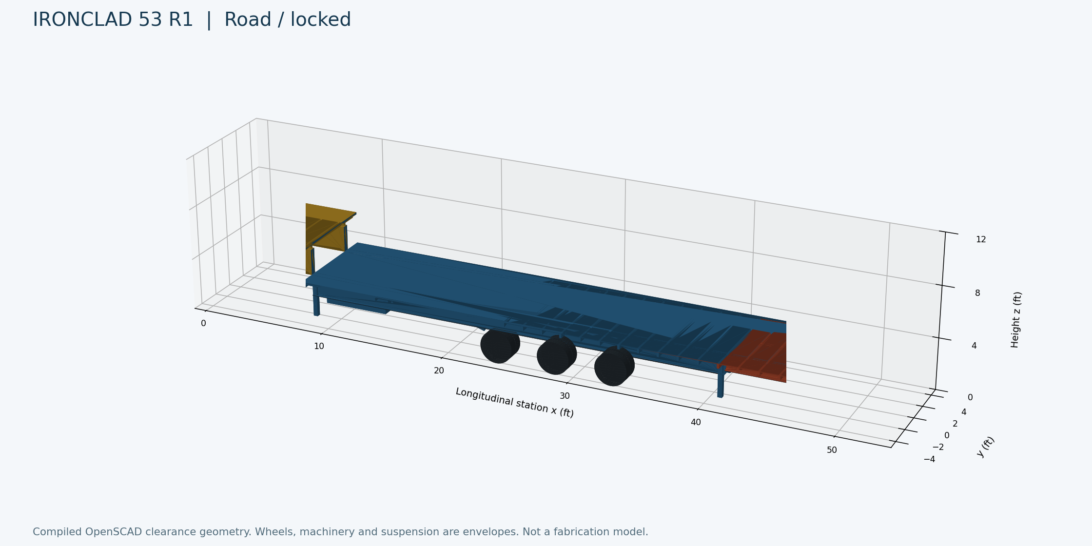
Compiled coordinate model. Simplified tires, chassis and equipment envelopes; supplier interfaces remain unresolved.
02 tail down model
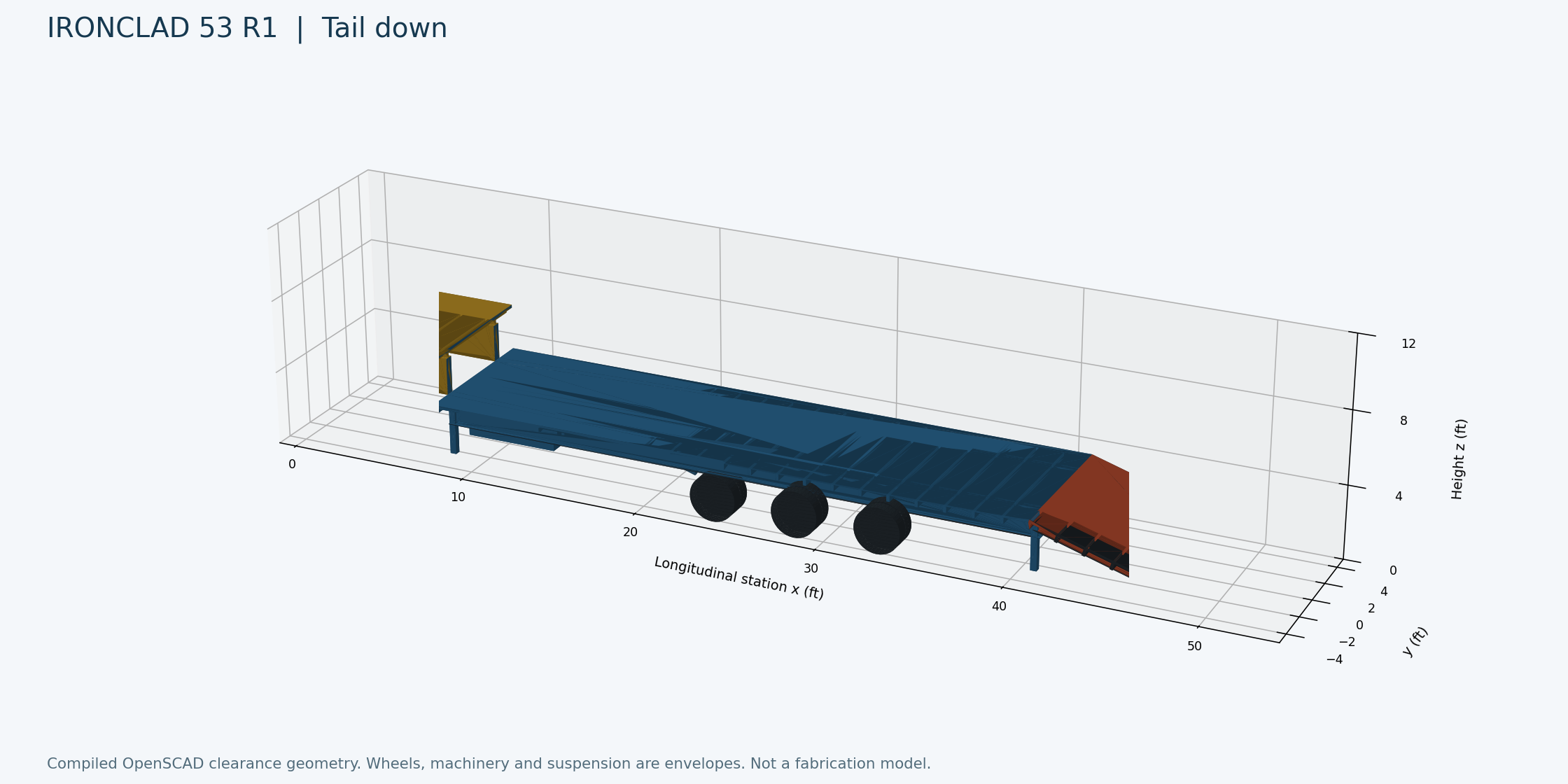
Compiled coordinate model. Simplified tires, chassis and equipment envelopes; supplier interfaces remain unresolved.
03 main tilt model
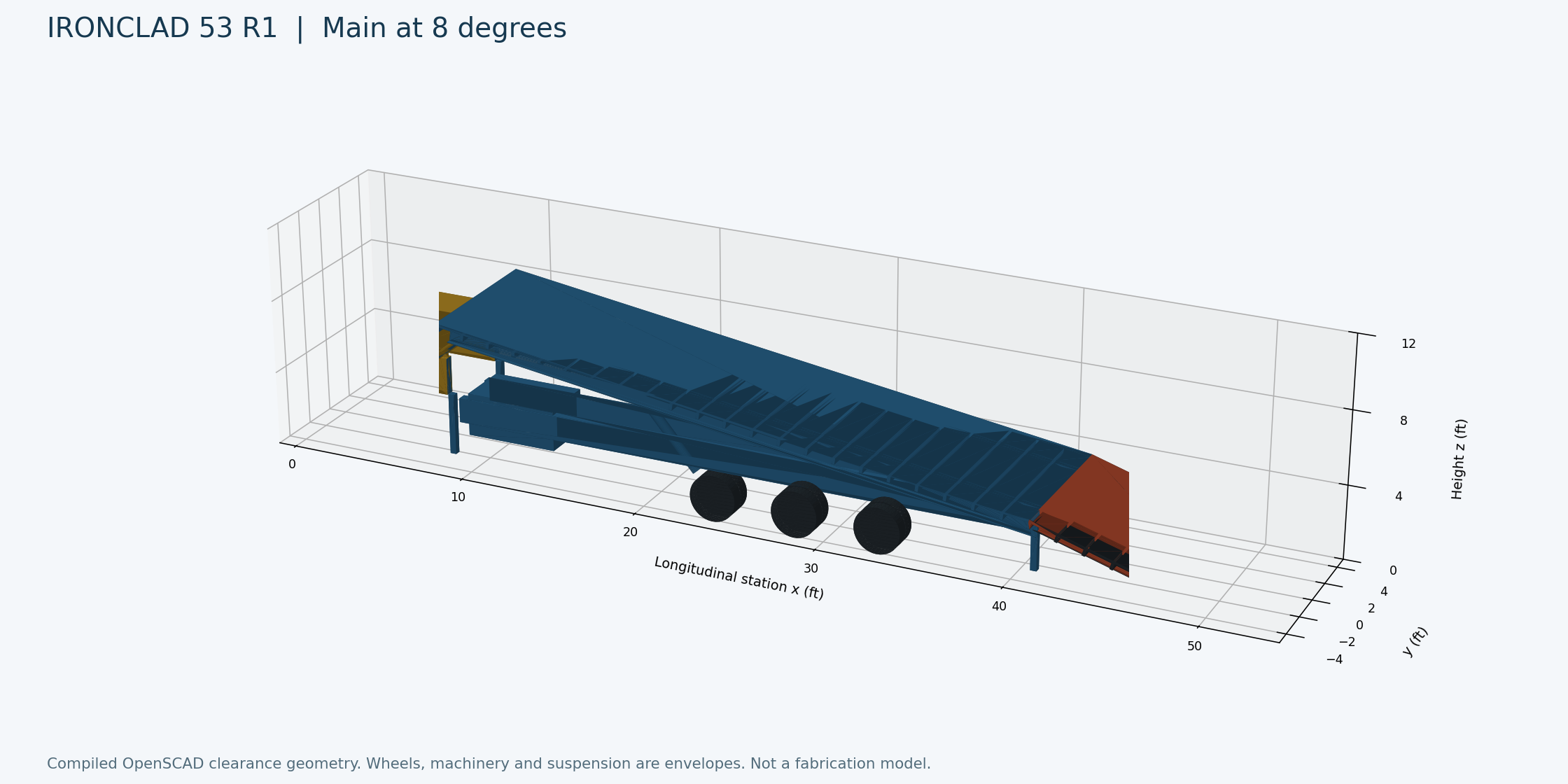
Compiled coordinate model. Simplified tires, chassis and equipment envelopes; supplier interfaces remain unresolved.
04 upper transfer model
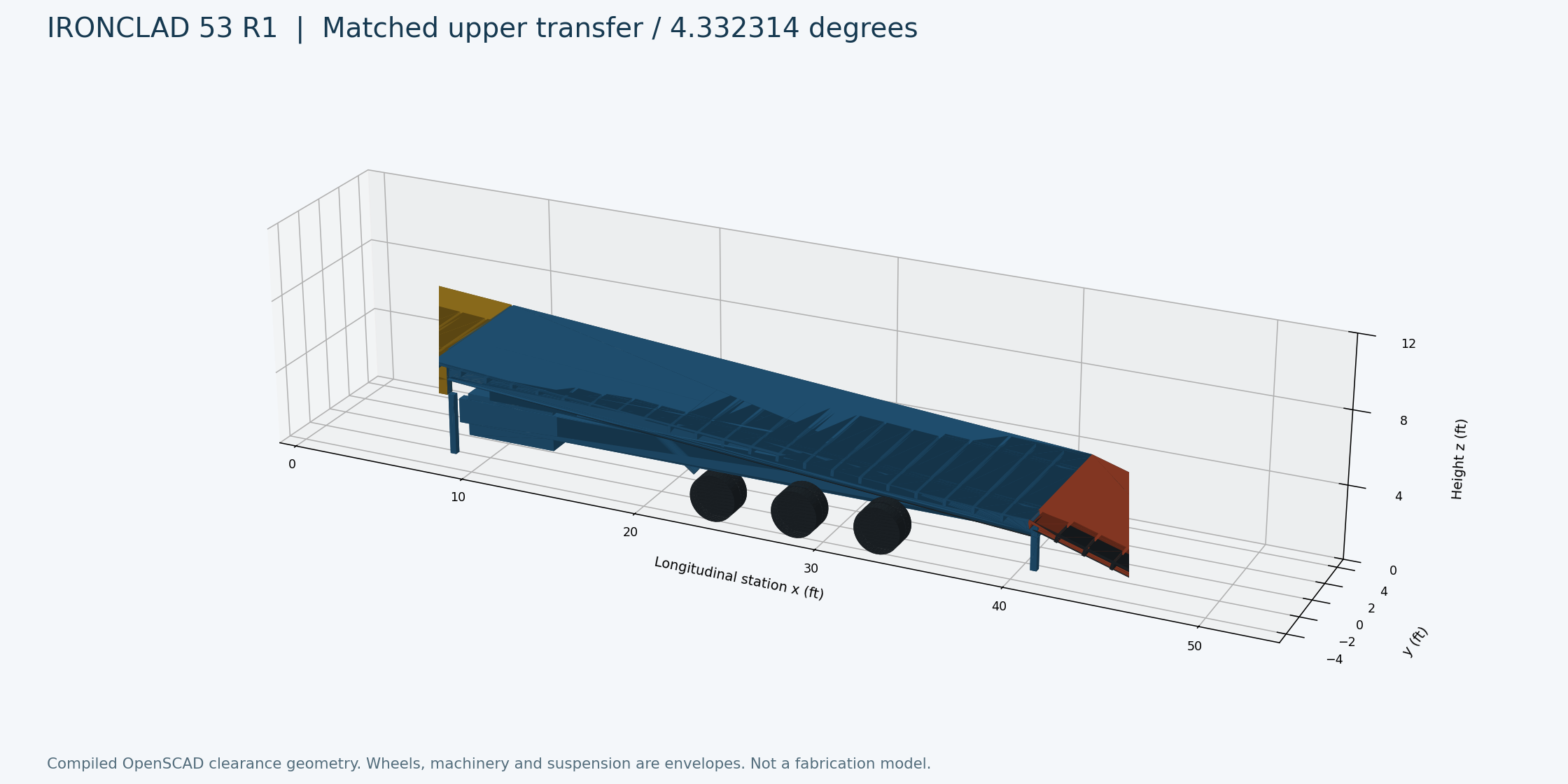
Compiled coordinate model. Simplified tires, chassis and equipment envelopes; supplier interfaces remain unresolved.
R1 P01 deck states
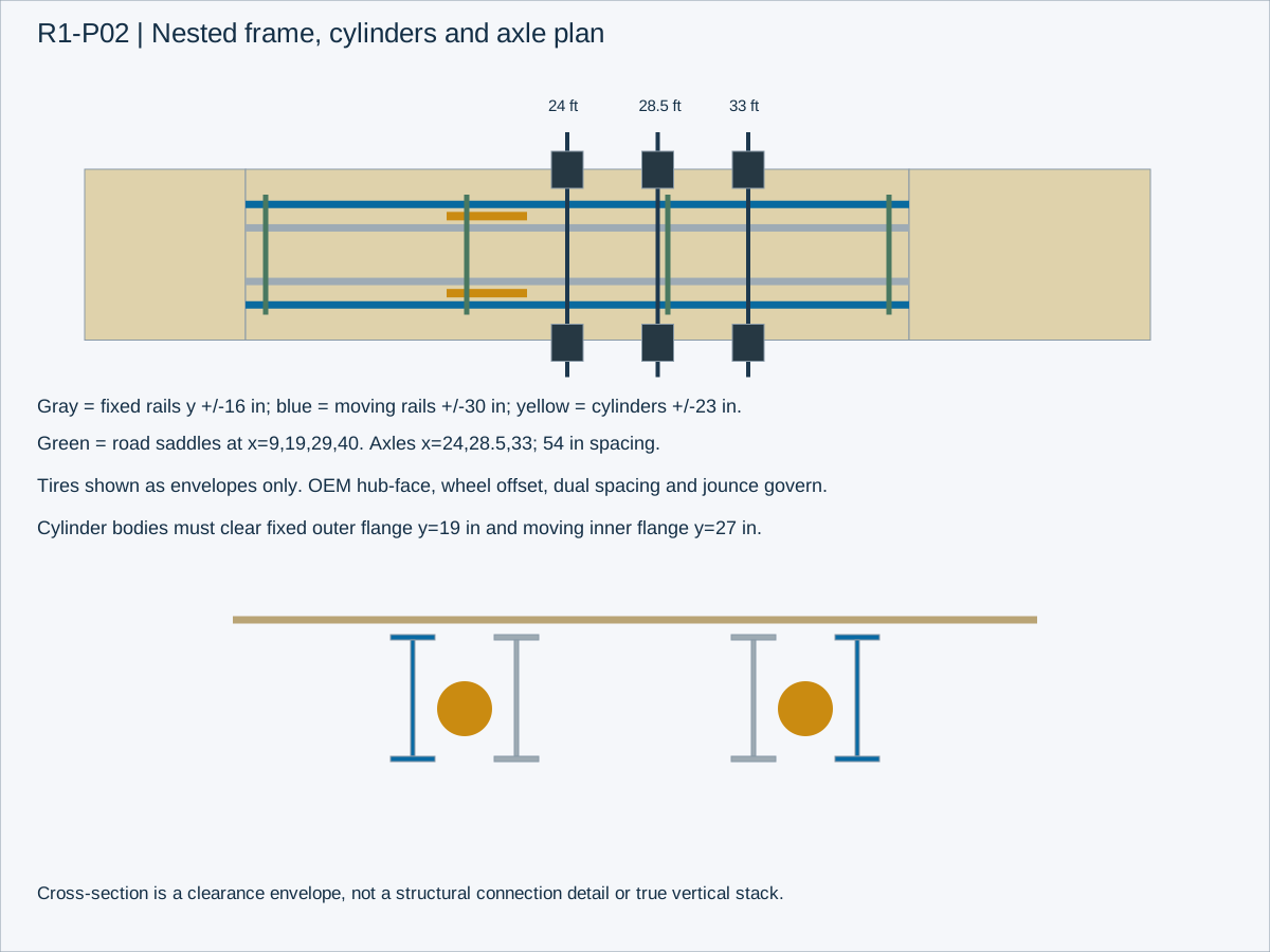
R1 P02 frame axle layout
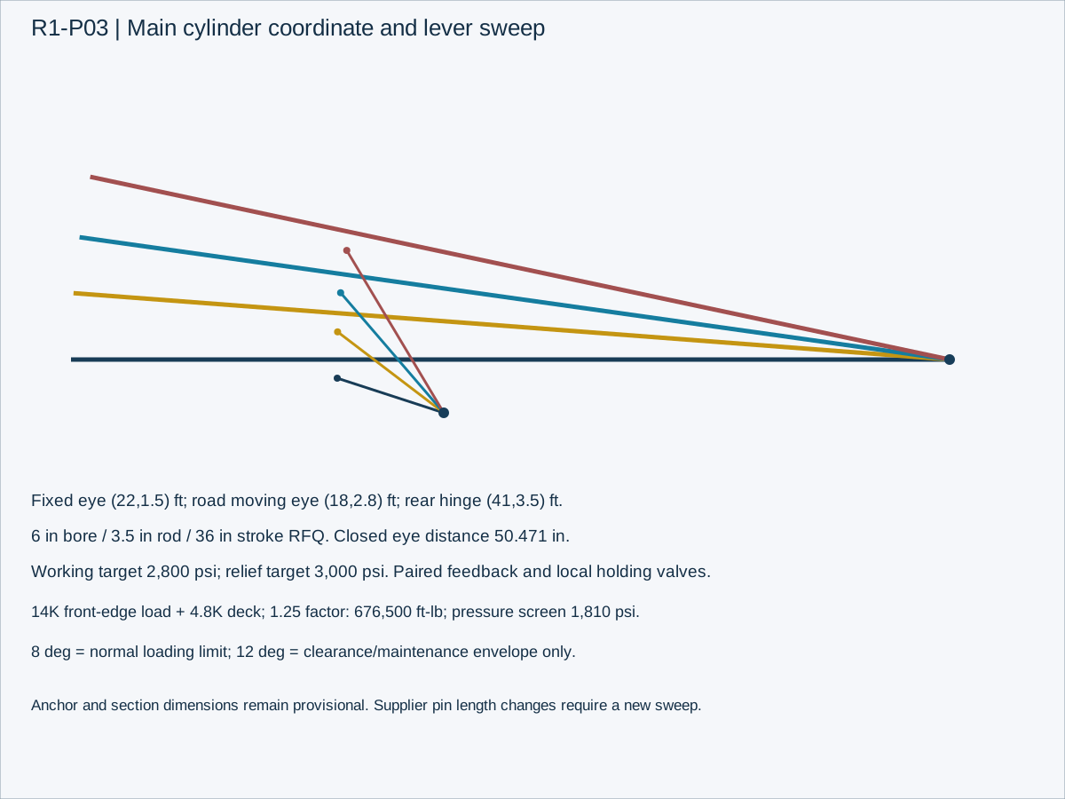
R1 P03 cylinder geometry
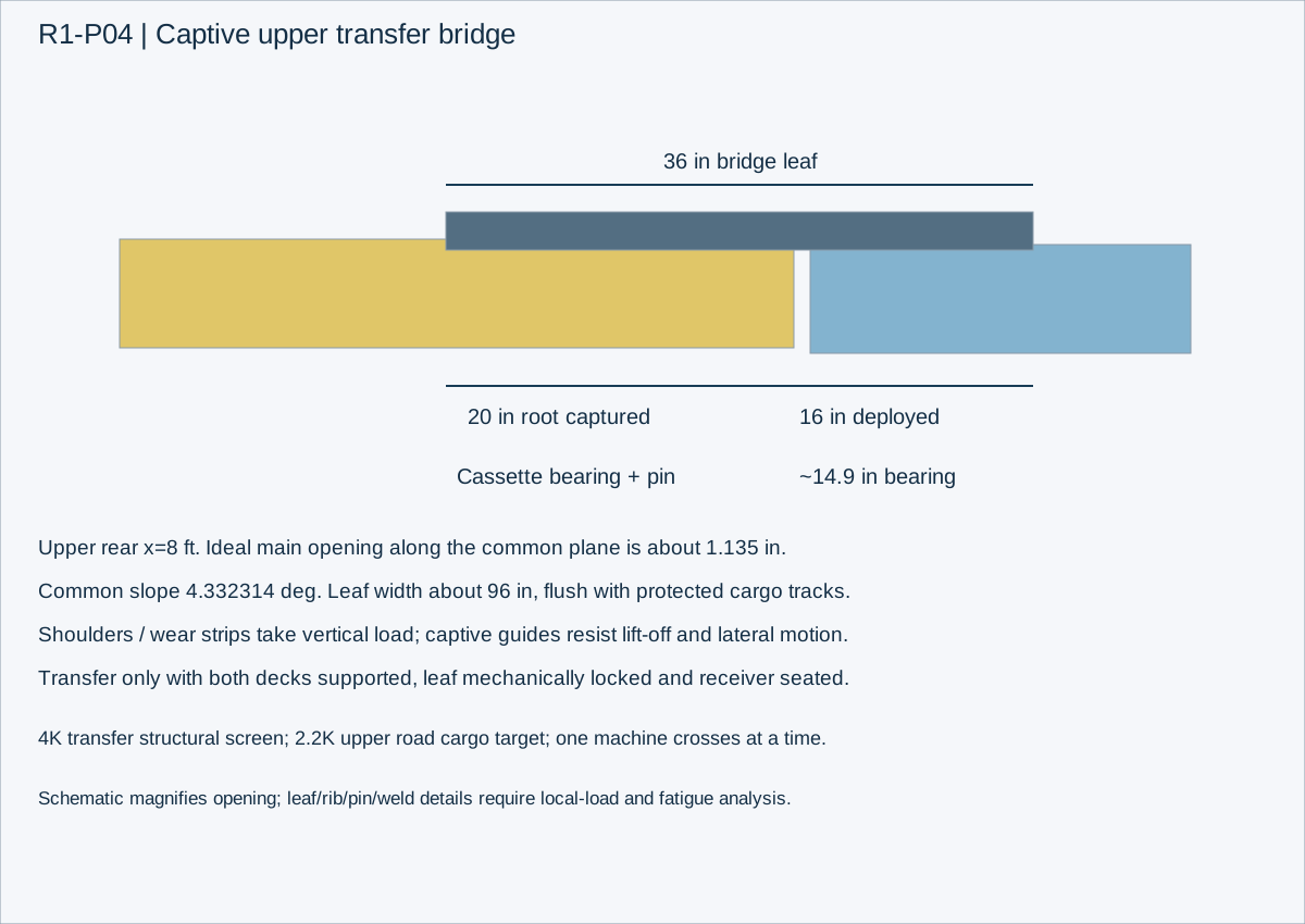
R1 P04 bridge bearing
R1 design decision: F-450 is the ceiling
Adam selected a crew cab 4x4 F-450 as the tow-platform baseline. Keep the 53 ft concept, 8 ft upper deck, 33 ft main, 12 ft hydraulic tail, twelve road tires, three axles, air ride, front lift axle, twin winches, engine HPU, substantial air compressor, cameras, recessed cargo tracks and lighting. Do not develop a larger-truck version as the primary design.
R1 replaces the R0 40,000 lb payload objective with a 14,000 lb main-deck structural/motion screening target and a provisional 33,000 lb gross operating envelope. This is a development target, not an assigned legal GVWR or towing authorization. Available cargo is gross minus actual tare; deck targets never add together to increase gross allowance.
With all requested systems, the material/assembly budget is approximately 19,700 lb before supplier weight confirmation. The TB260 or TL12V2 can individually fit the nominal mass envelope. Both together cannot. Upper-deck hauling remains useful for smaller-machine combinations; placing a skid above the hitch consumes a large share of the truck payload.
R1 supersedes R0 geometry, axle locations, load cases, main motion target and component-sizing assumptions. R0 renderings remain historical concept illustrations. The new dimensioned model is the geometry reference. No drawing in this revision is a shop-release drawing.
Truck envelope and configuration
Design assumption: 2026 F-450 pickup, crew cab, four-wheel drive, dual rear wheels, 8 ft box, 6.7 L high-output diesel, 4.30 axle. Ford towing guide v3, printed page 24, lists 37,100 lb gooseneck and 46,700 lb GCWR for that configuration. Standard-output diesel differs. The 40,000 lb headline belongs to a different regular-cab 4x2 configuration with the specific package.
Use a 33,000 lb trailer gross planning ceiling to leave room below the published tow rating. It does not create truck payload or axle margin. The model uses a 5,000 lb available hitch-load budget solely as a placeholder, and Ford's 15 percent gooseneck tongue-weight guidance as the load-placement target. At 33,000 lb, 15 percent is 4,950 lb: only 50 lb below the placeholder. Actual truck data may force a lower gross ceiling.
Required actual truck records: VIN/year, engine, axle ratio, tow package, certified GVWR/front and rear GAWR, payload label, tire capacities and pressures, hitch/coupler vertical and gross ratings, full-fuel scale weights with occupants and usual tools. A older/option-heavy truck may not satisfy this baseline.
Truck load increment with ball a distance e forward of rear axle and wheelbase L: front increment=pin*e/L; rear increment=pin*(1-e/L). With e=0, all pin load goes to rear axle. Compute allowable pin=min(GVWR minus ready truck weight, rear-axle headroom/(1-e/L), front-axle headroom/(e/L) when e>0, rated hitch/coupler vertical limit). Do not treat the rear receiver tongue-load rating as the in-bed gooseneck limit.
Gross limit=min(33,000 planning ceiling, actual model tow limit adjusted as manufacturer requires, actual GCWR minus ready truck weight, approved trailer GVWR, axle/tire/brake limits, available pin/0.15 for the target load ratio). Do not subtract pin from trailer weight in the GCWR calculation: ready truck weight plus complete trailer gross counts each pound once.
Weight budget with material checks
Nominal assembly sum is 19,700 lb at CG x=23.863 ft. Applying each line's upper allowance gives 24,472 lb. Upper allowances are an uncertainty envelope, not a statistical confidence interval. At a 33,000 lb gross ceiling, nominal payload is 13,300 lb; the high-weight case leaves only 8,528 lb.
The main deck cannot be budgeted as only its two longitudinal rails. Its 280.5 square feet of 2 inch wood at 40 lb/cu ft weighs about 1,870 lb; two 33 ft candidate 18 inch fabricated I-rails weigh about 1,574 lb; approximately 23 transverse members at 8.5 ft and 4.5 lb/ft add about 880 lb. Rails, edging and attachments put the moving deck near the 4,800 lb line. Wood species/moisture, actual crossmember profiles and tie-down rail weights must replace these assumptions.
The fixed frame allowance includes roughly 1,910 lb of paired 33 ft 16 inch fabricated beams, a heavy 8 ft neck pair, drops/transitions, crossmembers, gussets and lock saddles. Nest the fixed rails and moving rails laterally rather than stack both full beam depths beneath the deck. A full stacked double frame would consume the ground-clearance envelope.
The compressor, hydraulics, oil, winches and batteries forward of the main deck create a strong forward mass moment. Trailer tare CG must be calculated assembly by assembly and then measured, rather than adjusted arbitrarily to reduce hitch load. R1 moves the axle/suspension mass along with the axle group.
| Assembly | lb | CG ft | High +% |
|---|---|---|---|
| Fixed chassis / neck | 4200 | 23 | 25 |
| Moving main deck | 4800 | 24.5 | 20 |
| Upper deck | 1000 | 4 | 25 |
| Tail | 1700 | 47 | 25 |
| Transfer bridge | 450 | 8 | 35 |
| Axles, brakes, suspension, lift | 1900 | 28.5 | 30 |
| Wheels, tires, two spares | 1400 | 27 | 20 |
| Landing gear / rear stabilizers | 500 | 27 | 25 |
| Main cylinders / mounts | 550 | 21 | 30 |
| Upper / tail cylinders | 250 | 28 | 30 |
| Engine / hydraulic pump | 450 | 9 | 20 |
| Oil / reservoir / cooling | 350 | 9 | 25 |
| Compressor / air equipment | 250 | 9 | 25 |
| Two winches / cable | 550 | 9 | 25 |
| Electrical / cameras / lights | 300 | 9 | 25 |
| Cargo anchors / rails | 600 | 26 | 25 |
| Finish / hardware allowance | 450 | 26 | 25 |
Dimensioned road geometry
All longitudinal stations x are feet from the foremost upper-deck edge, not from the hitch ball. Lateral y is inches from centerline. Height z is feet above level ground at normal suspension ride height. Width is 102 inches maximum concept envelope including rub rails. Actual coupling, wheel track and clearance geometry comes from selected suppliers and the truck.
Fixed chassis ends at the tail root x=41. Rear stabilizers attach to the fixed frame near x=40.5; they must not be placed on the moving tail. Front hydraulic landing legs are near x=9. The machinery bay remains between the front legs, with exhaust/heat and hose routing isolated from the truck and cargo.
Upper deck extends forward of the ball by 18 inches with the provisional ball x=1.5. Its corners sweep a roughly 4.51 ft radius in plan. A 72 inch deck surface is not proof of roof clearance; deck underside, forward cargo, neck knees and an articulated turn must be checked against actual truck CAD/measurements. Use 90 degree yaw and the required pitch/roll articulation envelope as collision cases; choose operational limits from actual clearance rather than promising jackknife capability.
| Feature | R1 station / dimension |
|---|---|
| Upper deck | x=0..8; rear hinge (8,6); 96 in useful width inside rails |
| Main deck | 33 ft true length; rear hinge (41,3.5); road front (8,3.5) |
| Tail | 12 ft true length; independent hinge at (41,3.5) |
| Hitch ball assumption | x=1.5; height and adjuster span from actual truck |
| Axle centers | x=24.0 / 28.5 / 33.0 ft; 54 in adjacent spacing |
| Three-axle resultant | x=28.5 ft if equal sharing; actual OEM balance governs |
| Front lifted resultant | x=30.75 ft for equal sharing of remaining pair |
| Fixed rail centerlines | y=+/-16 in; initial 6 in flange-width envelope |
| Moving rail centerlines | y=+/-30 in; initial 6 in flange-width envelope |
| Main cylinder centerlines | y=+/-23 in; clearance pending actual OD/hoses |
| Rear stabilizers | fixed x=40.5; feet outside tire/loading paths |
Load placement and towing cases
For a simplified rigid trailer: R_hitch=sum[W_i*(A-x_i)]/(A-H), R_axles=sum W_i-R_hitch. H=1.5 ft and A=28.5 ft. Equal axle sharing is a screening assumption; it does not calculate individual wheel loads, suspension geometry changes or road dynamics.
Single-machine placement stations below target exactly 15 percent pin with the nominal mass budget. A CG station is not the machine's bumper, bucket tip or track midpoint. Determine machine CG from wheel/track reactions or manufacturer data, secure its attachments, then align the measured CG with the specified station. TB260 and TL12V2 weights are manufacturer configuration reference weights; weigh the actual machine with fuel, thumb, bucket and attachments.
The two-mini case uses two 4,400 lb assumed excavators and a 2,200 lb upper-deck skid. Its CG assumptions are independent of any stock illustration. Pack actual track lengths and booms in 3D; the model only evaluates longitudinal weight balance. The second CG at x=36 ft places its tracks near the main rear edge and may require nesting a forward-folded boom; footprint clearance is unresolved.
The nominal TL12V2 case has only 110 lb of trailer gross margin and 66.5 lb of pin margin against the illustrative limits. Its cargo CG placement window between a 15 percent target and 5,000 lb pin is only about 1.6 inches. That is too narrow to treat as a robust working load without actual weights and more truck pin capacity or less tare. These are feasibility screens, not ready-to-haul prescriptions. TB260 margin is also small. Design weight reduction and actual truck headroom must improve these margins before heavy-machine release.
The TL12V2 plus upper skid case fits below the published 37,100 lb tow maximum but exceeds the 33,000 lb R1 ceiling and 5,000 lb illustrative pin allowance at a 15 percent target. It stays outside the base envelope. The TB260 plus TL12V2 case is heavier than the published tow limit; changing axle position cannot repair that gross-weight failure.
Do not move cargo rearward until pin drops below the Ford 15 percent target just to make the truck payload arithmetic pass. Instead lower gross/cargo or change the supported configuration within F-450 options. R1 does not assume ballast or a rear trailer to compensate.
| Case | Gross lb | Pin lb | Pin % |
|---|---|---|---|
| Empty / all axles down | 19,700 | 3,383 | 17.17 |
| Cab TB260 only | 32,345 | 4,852 | 15.00 |
| Cab TL12V2 only | 32,890 | 4,934 | 15.00 |
| Two 4,400 lb minis + upper 2,200 lb skid | 30,700 | 4,972 | 16.20 |
| TL12V2 + upper skid / outside base envelope | 35,090 | 5,264 | 15.00 |
| TB260 + TL12V2 / rejected | 45,535 | 5,875 | 12.90 |
| Empty / front axle lifted | 19,700 | 4,638 | 23.55 |
Lift axle: empty is conditional
Empty all-down pin is 3,383 lb. Empty front-lift pin is 4,638 lb. Lifting shifts the resultant aft and INCREASES truck hitch load. The extra load must fit truck GVWR/rear GAWR as well as the remaining two suspension/tire/brake positions.
Specify three 12,000 lb dual-wheel hydraulic-disc axle positions with an OEM-engineered air-ride package, nominal 36,000 lb aggregate component capacity. Dexter documents D120 with DexAir tandem/triple applications. That is not proof a stock DexAir assembly accepts a homebuilt lift conversion. Obtain a packaged lift-enabled forward station or an approved separate compatible suspension from the suspension supplier; do not add lift bags to a stock arm without design approval.
Lift permission requires a validated empty-load signature, all deck transport locks engaged, bridge and portable lights stowed, adequate protected air reserve, acceptable truck/remaining axle loads and suspension supplier speed/pressure limits. Disable lift for loaded travel and all loading motions. Default axle down on command/sensor fault using an approved pressure/valve sequence; do not drop an axle abruptly at speed.
The equal-share empty remaining-axle load is a useful limit check only. Unequal side loading, road crown, pressure and articulation can load one wheel or air spring more than the group average. Calibrate a load display against certified axle-scale tickets in both axle states.
Exact transfer kinematics and bridge
The correct common-plane angle is atan((72-42)/(33*12))=4.332314 degrees, not the R0 asin calculation. Both rigid decks need the same slope and the same supporting line. Main front at this angle is x=8.094291 ft, z=5.992857 ft; it sits slightly aft and below the upper hinge, on the common inclined plane.
Upper front is x=0.022858 ft, z=6.604329 ft. Longitudinal opening is 1.131 inches; vertical difference is 0.086 inches. These values describe ideal rigid geometry only. Manufacturing, frame deflection and bearing tolerances need their own budget.
Use a 36 inch long, approximately 96 inch wide captive sliding bridge leaf in the upper rear cassette, hydraulically deployed 16 inches along the common deck slope. Approximately 20 inches remain captured in the cassette and about 14.9 inches bear on the main-deck receiver in ideal geometry. Stop against steel shoulders and engage a positive transverse lock before a machine crosses. Hydraulic pressure alone is not a load support.
Leaf travel is unloaded only. The cassette and main receiver carry the vertical load through replaceable wear strips/rollers and bearing shoulders. Add funnel guides for alignment, debris drainage, removable inspection covers and protected pinch zones. Two independent seated/bearing confirmations plus the mechanical lock indication permit transfer; a cylinder-position switch alone is insufficient.
Upper moving deck and bridge structural transfer target is 4,000 lb, one compact machine at a time; nominal upper road cargo target is 2,200 lb, subject to total hitch/gross balance. Main and upper deck motions are inhibited with cargo on the bridge. No deck moves while a machine straddles a hinge or bridge.
The bridge requires local wheel/track patch-load analysis, side loading, torsion, wear, capture retention and receiver fatigue. Its 450 lb assembly allowance is provisional. An unreinforced flat plate is not the design. R1 fixes its travel/bearing geometry but does not release plate/rib thickness or welded details.
Main lift: direct paired cylinder geometry
Replace the underspecified R0 lift scheme with two direct-acting cylinders. Each fixed base eye is (x=22,z=1.5), and its road-state moving eye is (x=18,z=2.8), in feet. Main hinge is (41,3.5). Both cylinders are positioned at y=+/-23 inches. This arrangement provides a finite lift lever at zero angle and keeps cylinder bodies ahead of the forward axle.
Screening cylinder geometry: 6 inch bore, 3.5 inch rod, 36 inch nominal stroke. Required road-state pin-to-pin distance is 50.471 inches, which is a vendor RFQ dimension, not a claim an off-the-shelf cylinder fits. Anchor coordinates must be adjusted if the selected closed length differs, then the full lever/stroke/clearance sweep rerun.
Normal main loading motion is 0..8 degrees. Transfer is a separate controlled 4.332314 degree position. The 12 degree state remains a clearance/maintenance envelope only and must not be enabled as a general operating preset. Mechanical travel stops prevent exceeding the approved stroke and deck angle.
For 14,000 lb cargo at the FRONT edge plus a 4,800 lb uniformly distributed moving deck, a 1.25 screening multiplier produces 676,500 ft-lb about the rear hinge. Minimum calculated cylinder lever is 7.775 ft. At 85 percent force-efficiency assumption, the paired bores require 1,810 psi. At a 2,800 psi working ceiling, modeled moment capacity is 1,046,365 ft-lb. This is a static lever screen, not a certified motion capacity.
A manifold flow divider alone does not guarantee position synchronization under unequal cargo. Use paired angle/position feedback with independently modulated valves, local load-holding/counterbalance valves at both cylinders and a stop on differential error. The stiff main torsion structure must carry transient imbalance without transferring uncontrolled loads to a single rod.
Conservative pin-to-pin Euler screening at the 12 degree state gives approximately 290,226 lb for a 3.5 inch solid steel rod with E=29 million psi and pinned ends. Dividing by 3 leaves 96,742 lb, compared with approximately 51,184 lb per-cylinder required static force. Cylinder maker must check its actual gland/piston/end conditions, rod unsupported length, side load and pressure rating; the simple Euler result is not a purchase release.
| Main angle | Eye x / z ft | Eye distance in | Lever ft |
|---|---|---|---|
| 0.0000 | 18.000 / 2.800 | 50.471 | 7.775 |
| 4.3323 | 18.013 / 4.539 | 60.163 | 13.109 |
| 8.0000 | 18.126 / 6.008 | 71.322 | 15.714 |
| 12.0000 | 18.357 / 7.597 | 85.232 | 17.336 |
Steel structure screening and load paths
Moving main rails candidate: paired fabricated I sections, 18 inch overall depth, 6 inch flanges, 5/16 inch flange thickness and 3/16 inch web. Symmetric section I=375.3 in^4, Z=41.70 in^3, nominal area=7.008 in^2. These are geometric properties, not an approved section schedule. Use material certificates and traceable steel; unspecified scrap cannot inherit a 50 ksi design assumption.
A deliberately severe front overhang screen places the entire 14,000 lb cargo at x=8 with cylinder reaction near x=18. Each rail sees about 7,000 lb at a 10 ft overhang plus its local distributed deck weight. At a 1.25 multiplier the approximate bending stress is 26.5 ksi. Against an illustrative 0.6Fy=30 ksi screen for 50 ksi steel this is only one section check; do not infer a pass for fatigue, deflection, buckling or full frame strength.
Analyze the deck in motion as a rear-hinge and inclined-cylinder supported structure with a front overhang; road service uses steel support saddles near x=9,19,29 and40. Rear hinge carries the vertical and horizontal cylinder-induced reactions. Fixed base crossmember at x=22 takes paired cylinder pushes into the fixed longitudinal rails. Saddles carry road vertical load; locks retain decks and take specified braking/side loads through shear keys.
Candidate fixed chassis rails: 16 inch fabricated I depth with 6 inch x 3/8 inch flanges and 1/4 inch web. Gooseneck/drop transition needs a separate reinforced design for combined bending/torsion, welded fatigue details and coupling forces. Flange/section changes require tapered transitions and weld sequencing reviewed for distortion and fatigue.
Moving/fixed rails overlap in height but are offset laterally. Initial envelopes: fixed 6 inch flanges centered y=+/-16; moving 6 inch flanges centered y=+/-30; cylinder OD fits the 8 inch lateral slot between adjacent flange edges, near y=+/-23. Hose loops, glands, clevis swing, fabrication tolerances and cylinder OD can consume this entire gap. Increase deck/chassis layout clearance if supplier dimensions require it; do not grind structure to fit.
Required load cases: 14K front/center/rear main, one track at a time crossing the tail, diagonal track contact, 4K bridge crossing, 2.2K upper road cargo, air-suspension bottom-out, side slope, braking, winch stall and two-line pulls, deck synchronization fault, tail ground impact and lock failure load redistribution. Analyze individual D-ring/chain slot paths; slots stay in reinforced secondary modules, not unreviewed primary flanges.
Mechanical locks and service supports
Use mechanically engaged seats plus paired captive locking pins for each deck. The cylinders unload into steel seats for transport. Replaceable shear keys locate the deck longitudinally/laterally, and tapered guide entrances aid docking; the tapered entrance is not the pin's rated load-bearing land. Full cylindrical engagement is separately sensed at both sides.
Main road seats near x=9,19,29,40 distribute vertical load into the fixed frame. Main rear hinge is permanently retained. Front/mid pairs of pins prevent opening under road shock; individual pin/lug brackets must be checked for relief-limited cylinder force and differential twisting. Pins are captured with secondary positive retention and can be released only after cylinders take load.
Upper deck bears on neck saddles in road mode, with two independent locks across the frame width. Transfer position uses positive structural bearing/props at the matching angle so the bridge receiver does not depend on a floating hydraulic deck. Tail road seats and paired locks near its hinge/root hold the tail flat; a separate mechanical retention feature secures the tail in any approved raised/up position.
Use an OEM-equivalent spring-engaged, powered-release principle only after detailing its positive retention; springs do not substitute for full pin engagement. A cam/hook lock may be substituted if its manufacturer provides ratings and a compatible approved mount. No claim of the best industry lock is made without a tested component selection.
Maintenance props are independent of transport locks and local hydraulic holding valves. Store them captively, provide visible full engagement, and size them for the approved maintenance load. Hydraulic valves hold position during operation; mechanically blocked structure supports people working beneath a deck. Release drawings must give pin material, diameter, fits, lug thickness, bearing lengths, welds, torque and inspection/replacement limits.
Upper, tail and support motion
Upper rear hinge remains fixed at (8,6); raising the forward edge by about 7.25 inches matches the main plane. Use two compact direct cylinders or one cross-shaft actuation system that provides torsional stiffness and position supervision. Rate for the 4K transfer target plus moving deck mass and the worst allowed CG. Cylinder/mount dimensions await truck cab and neck-envelope verification.
Tail ground angle at 42 inch hinge height is 16.958 degrees; toe station is x=52.478. Thus a rigid 12 ft tail alone is relatively steep. Air kneeling is not assumed while loading unless the suspension OEM approves support height and load paths. Use a short toe bevel/hinged toe or an approved ride-height/loading sequence to reduce breakover; do not casually command air dump with a loaded deck moving.
Tail load target is a single 14,000 lb machine crossing with ground-supported toe and deployed fixed-frame rear stabilizers. Tail lifting with that full machine on it is not approved by the target. Keep the tail clear during folding/raising except for the manufacturer-approved limited incidental load. The load case needs track-entry impact and one-side contact, not only a uniform area load.
Keep the trailer coupled while deploying motion supports. Front legs stabilize the machinery/neck area without lifting the truck rear axle; rear supports near x=40.5 prevent excessive tail-root reactions into the truck. Feet need appropriately sized pads/cribbing and level ground. Support reaction/load cells and angle sensors should inhibit motion beyond the validated support envelope.
Before allowing upper transfers, evaluate the temporary load as the machine crosses from main to bridge to upper. Final road balance alone does not prove intermediate stability or support capacity. The dynamic CG traverses a forward path and raises; bound speed and require a spotter/clear exclusion area.
Upper and tail actuator coordinate screens
Upper provisional paired cylinder eyes: fixed base (4,5.0) ft; road moving eye (2,5.4) ft; deck hinge (8,6) ft. Place laterally within the neck using actual bed-rail/cab clearance. At road position the eye distance is 24.475 inches and perpendicular moment arm about 1.765 ft. A pair of 3 inch bore cylinders needs about 2,122 psi for a 4,000 lb machine at the upper front plus a 1,000 lb deck centered 4 ft from the hinge, using 1.25 moment factor and 85 percent efficiency. This actuator fits the power envelope; its below-deck packaging is unverified.
At the matched 4.332314 degree transfer position, the moving upper eye is approximately (1.972,5.855) ft; eye distance about26.411 inches. A nominal 3 inch bore / 1.75 inch rod / 8 inch stroke cylinder is an RFQ starting point, with 24.475 inch road closed-length target. Final stops need only the approximately1.94 inch modeled extension and must not expose the unused stroke as additional permitted motion. Vendor mounts, exact closed length and truck clearance govern.
Tail provisional paired eyes: fixed base (38,1.8) ft and road moving eye (44,2.8) ft; independent tail hinge (41,3.5) ft. The eye distance is72.993 inches and road lever1.184 ft. Lowering the tail to ground retracts the cylinders to about68.0 inches. This long, nearly horizontal layout is an envelope example, not a standard-cylinder claim; adjust anchors for actual closed/retracted pin lengths after supplier selection.
A pair of 3.5 inch bore / 1.75 inch rod cylinders screens at approximately660 psi to raise only the 1,700 lb tail centered6 ft aft of its hinge, with1.25 multiplier and85 percent efficiency. Select pressure/holding-valve settings for controlled deadweight lowering. Ground-supported14K machine traversal is a separate structural load case. These cylinders do not authorize raising a14K-loaded tail.
Upper and tail pairs need the same synchronization/angle and local holding-valve provisions as the main pair. Cylinders must not be used as hard mechanical stops. Tail toe position, road seats and the neck bearing geometry may force a different actuator layout; every change requires a fresh moment-arm and stroke sweep.
Hydraulic power, air and cycle time
Keep Honda iGX800-class engine power and the substantial VMAC H40-class hydraulic compressor in the front bay. R1 retains the R0 power balance: use about 8 GPM at high pressure for motion; compressor supply may need a dedicated 9..12 GPM branch at its manufacturer pressure. Compressor and heavy winch/deck motions are mutually exclusive engine-load modes, not simultaneous full-rated loads.
For two 6 inch bores, 0..8 degree extension adds 20.85 inches of stroke and approximately 5.10 gallons of cap-end volume. At an actual delivered 8 GPM, ideal extension is 38.3 seconds; metering/feedback slows it. Full 36 inch stroke uses 8.81 gallons. Size reservoir usable level and return headspace using all cylinder displacement states, not just nominal fill volume.
6 inch / 3.5 inch rod annular area is about 18.65 square inches. For gravity-assisted lowering, cap-end return can exceed pump inlet flow because of area ratio; calculate peak return/counterbalance/filter/cooler flow at commanded lowering speed. The motion return circuit and tank breathing must handle that peak without cavitation or pressurizing the tank.
Retain roughly 40 gallon shell / 30 gallon working reservoir as an RFQ baseline until upper/tail/landing cylinders and compressor motor are selected. Low-level, temperature and suction-pressure monitoring protect the system. Reservoir, filters, cooler, priority manifold and exhaust shielding all stay in the weight budget.
Protect suspension air reserve with priority/check valves and separate service-air draw. Keep two initial 10 gallon certified receiver allowances and a small independent maintenance compressor for parked leveling/emergency reserve. VMAC is a supplier candidate; verify pressure, CFM, duty, oil/cooling, required flow and receiver arrangement before buying.
Main hydraulic winch remains a 20K first-layer candidate for recovery margin, not an authorized 20K pull on every trailer attachment. Upper winch nominal 8K motor/winch option is line-pull-limited to the upper/bridge structural envelope. Winch anchors, sheaves, two-part reeving and vehicle attachment points require actual force/load-case checks.
Electrical, cameras, cargo and lighting
The separate wiring branch continues: hardwired 12 V truck road lighting/brake circuits and dedicated EOH breakaway supply; separate fused 24 V house distribution and motion controls. Never route service braking through the wireless hydraulic remote. A Hydrastar 1,600 psi disc-brake actuator is a candidate only if Dexter/Hydrastar approve its volume, response and controller compatibility for the exact six-caliper assembly.
Road-ready permission requires all six deck lock-side indications, bridge stow, winch/stow retention, portable light stow and allowed lift state. Wired deadman controls and local E-stops remain available. Loss of radio commands safe hold through local hydraulic valves; it does not command an automatic deck return. Cameras provide visibility, not a substitute for bearing/lock sensors.
Retain rear center camera, two upper-side down/back cameras and three cargo/bridge/loading cameras. Wiring must accommodate every moving hinge using guarded loops with minimum hose/cable bend radii and strain relief. Put connector joints in accessible sealed junction points, not buried in a welded frame.
Retain two recessed cargo tracks and separate slider rails across all three decks, with isolated hinge cutbacks. Keep 4 inch strap stations at approximately 40 inch spacing, many rated D-rings and reinforced chain slots, stake pockets and rub rails. Exact station count and securement WLL follow the actual cargo layout and structural anchor design.
Keep the generous flush loading/underdeck lights, portable tethered magnetic pods in flush lockers, road markers and independent amber warning circuits. Road lamps keep their required function/color/visibility; work-light glare must not obscure road signals. The light inventory stays in R0 BOM pending fixture weight/current verification.
Procurement changes and release order
The R1 delta CSV below modifies procurement targets without silently turning an allowance into a released part. Existing R0 quantities for cameras, lights, cargo rails and protective controls remain traceable. Avoid buying long-lead custom axles, cylinders or main members until the corresponding interface geometry is approved.
Release order: actual truck records and scale envelope; certified suspension/dual-wheel/lift dimensions and masses; exact deck/neck articulation and clearances; structural analysis and weld detail; cylinder/mount/lock supplier review; final hydraulic/electrical schematics; complete weighed BOM; manufacturing drawings and inspection plan; stationary proof/functional tests; brake response and road validation. Assign the legal manufacturer/certification process before a road-use unit is delivered.
A useful supplier RFQ includes the R1 coordinate sheets and engine/load data, requests exact assembly weights and mounting drawings, asks for allowable ride-height/jounce/roll envelopes and brake torque/pressure/volume, and specifically asks whether the front station can be lifted in the stated empty reactions. An RFQ response, not a catalog image, resolves these interfaces.
Sources and boundaries
Ford 2026 RV & Trailer Towing Guide v3, printed page 24 for F-450 crew cab 4x4 HO ratings and tongue-load guidance; page 10 for hitch ball gross ratings. https://www.ford.com/content/dam/brand_ford/en_us/brand/towing/pdf/2026-Ford-RV-and-Trailer-Towing-Guide-v3.pdf
Dexter DexAir medium duty overview and Bulletin 475 identify D120 tandem/triple applications. https://www.dextergroup.com/dexair ; https://www.dextergroup.com/user_area/content_media/raw/pb475_DexAir.pdf . Front lift adaptation remains unverified.
Hydrastar GEN 8 1,600 psi disc actuator candidate: https://hydrastarusa.com/products/hydrastar-electric-over-hydraulic-eoh-trailer-mounted-brake-actuator . Exact six-caliper D120 compatibility and response need written selection.
Machine weight references remain the R0 source register: TB260 enclosed-cab reference 12,645 lb; TL12V2 reference 13,190 lb. Use actual weigh tickets, attachments and CG measurements for loading.
All R1 mass, reaction, geometry, cylinder and beam values are calculated assumptions/screens developed for this concept. No supplier has approved R1. The model omits elastic deflection, detailed suspension kinematics, dynamic stability and truck collision surfaces. No certified capacity, fabricator liability or regulatory approval is implied.
Weight reduction program before heavy-machine release
The retained 53 ft three-deck package is near the limit for the chosen truck. Set a 17,500 lb tare development goal while keeping the current 19,700 lb quantified baseline as the load-model default. A goal is not permission to replace calculated mass with a convenient value. At17,500 lb, single TL12V2 gross falls to30,690 lb and a15 percent pin target is4,603.5 lb; that gives appreciably more margin than the present nominal case.
First investigate OEM-rated lightweight deck panels on steel framing and replaceable steel track wear strips. About451 square feet of deck area means each1 lb/sq ft reduction saves451 lb. Replacing a6.67 lb/sq ft wood assumption with a verified4 lb/sq ft complete deck assembly could save roughly1,200 lb before wear-strip/fastener/isolation weight. Hollow aluminum or composite panels need actual wheel/track patch-load ratings, span support, traction and grouser-wear review; no product is selected here.
Then obtain actual axle/suspension and wheel assembly weights. Aluminum wheels may save a few hundred pounds across twelve road wheels plus spares, but dual wheel rating, offsets, fasteners and tire clearance take precedence. Reduce crossmember and gusset mass only after patch-load, fatigue and torsion analysis. A few hundred pounds from an optimized fixed-frame/neck structure is a study allowance, not a sanctioned reduction.
Require a supplier weight-return sheet for every large assembly, and maintain mass/CG revisions as mounts change. Do not trade away brake capacity, mechanical supports, air reserve, lighting, bridge capture or structural margins to hit a spreadsheet target. Large winch capacity and full53 ft length remain especially expensive in weight; those tradeoffs stay visible rather than being changed without Adam's decision.
Acceptance milestone for any heavy-machine road configuration: measured ready tare, measured actual machine and attachment weight, a practical CG/tie-down window, truck and trailer scale tickets with usable reserve, and cleared structural/suspension/brake interfaces. If the actual truck cannot support the needed pin, retain the F-450 ceiling and restrict that configuration's cargo; do not continue designing around a larger truck.